


47
1
5
9
3
7
11
2
6
10
4
8
12
13
14
11 – Communications (continued)
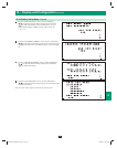
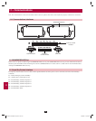
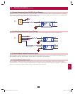
11-4 Remote Emergency Power Off (EPO) Circuit Diagram
The Remote Emergency Power Off (EPO) input connection (P1) allows you to connect the UPS system to your facility’s EPO circuit. Connecting
the UPS system to the EPO circuit enables remote emergency shutdown of the UPS system’s output. Connect EPO input to a user-supplied remote
switch, following the circuit diagram below. This contact is normally open.
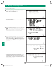
11-5 Auxiliary Dry Contact Input Circuit Diagram
The auxiliary dry contact input connections (P2) allow the UPS system to receive external signals. These contacts are normally open.
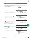
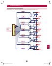
11-6 External Battery Cabinet Temperature Inputs
The external battery cabinet temperature input connections (P3, P4, P5, P6) allow the UPS system to receive signals from an optional accessory
that monitors the temperature of external battery cabinets. Call +1 773 869 1234 for more information.
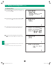
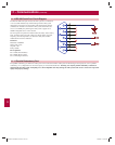
11-7 External Battery Status Input
The external battery cabinet status input connection (P7) allows the UPS system to receive external battery cabinet status signals through an
optional cable. Pin 1 = +12V; Pin 2 = detection cable connected; Pin 3 = battery cabinet breaker status (signal active= breaker on; signal inactive =
off); Pin 4 = reserved; Pin 5 = reference voltage. Call +1 773 869 1234 for more information.
P1
P2
200706017 93-2688 SU manual 4C.indd 47200706017 93-2688 SU manual 4C.indd 47 11/29/2007 2:03:03 PM11/29/2007 2:03:03 PM