


1
5
9
3
7
11
2
6
10
4
8
12
13
14
2
Table of Contents
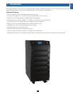
1 Introduction 3
2 Important Safety Instructions 4
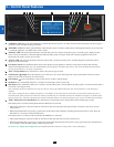
3 Control Panel Features 6
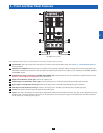
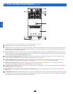
4 Front and Rear Panel Features 7
5 Cabinet Installation 9
5-1 Preparation 9
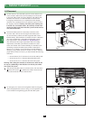
5-2 Unpacking 9
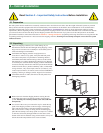
5-3 Placement 10
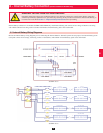
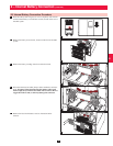
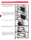
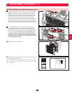
6 Internal Battery Connection 11
(Models SU20KX and SU40KX Only)
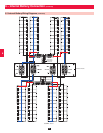
6-1 Internal Battery Wiring Diagrams 11
6-2 Internal Battery Connection Procedure 13
7 Wiring 16
7-1 Wiring Warnings 16
7-2 Wiring Preparation 16
7-3 UPS System Terminal Block Diagram 17
7-4 External Battery Cabinet Wiring Diagrams 17
7-5 Electrical and Cable Data 18
7-6 External Battery Cabinet Wiring 19
7-7 AC Input/Output Wiring (Single UPS) 20
7-8 AC Input/Output Wiring (Parallel UPS – Single Input) 21
7-9 AC Input/Output Wiring (Parallel UPS – Dual Inputs) 21
8 Operating Modes 22
8-1 Online (Normal) Mode (Single UPS) 22
8-2 Battery Backup Mode (Single UPS) 22
8-3 Auto Bypass Mode (Single UPS) 22
8-4 Manual Bypass Mode (Single UPS) 22
8-5 Online Mode (Parallel UPS) 23
8-6 Battery Backup Mode (Parallel UPS) 23
8-7 Auto Bypass Mode (Parallel UPS) 23
8-8 Manual Bypass Mode (Parallel UPS) 24
8-9 Hot Standby Mode (Parallel UPS) 24
9 Start-Up, Shutdown and Bypass 25
9-1 Control Panel and Breaker Diagrams 25
9-2 Preliminary Checklist (Single UPS) 25
9-3 Normal Start-Up Procedure (Single UPS) 25
9-4 Battery Start-Up Procedure (Single UPS) 26
9-5 Manual Bypass Procedure (Single UPS) 27
9-6 Shutdown Procedure (Single UPS) 27
9-7 Preliminary Checklist (Parallel UPS) 28
9-8 Start-Up Procedure (Parallel UPS) 29
9-9 Shutdown Procedure (Parallel UPS) 30
9-10 Manual Bypass Procedure (Parallel UPS) 31
9-11 Switching from Manual Bypass to Normal (Parallel UPS) 32
10 Display and Configuration 33
10-1 Control Panel Diagram 33
10-2 Display Hierarchy 33
10-3 Default Display 34
10-3-1 Status Display 34
10-4 Main Menu 37
10-5 UPS Setup 39
10-5-1 Bypass Setup 40
10-5-2 Output Setup 41
10-5-3 Battery Setup 43
10-5-4 Charger Setup 46
10-5-5 Parallel Setup 47
10-5-6 Control & Test Setup 48
10-5-7 Local Setup 50
10-6 Maintenance 53
11 Communications 55
11-1 Communications Interfaces 55
11-2 SNMPWEBCARD Slot 55
11-3 Input Dry Contact Interface 55
11-4 Remote Emergency Power Off (EPO) Circuit Diagram 56
11-5 Auxiliary Dry Contact Input Circuit Diagram 56
11-6 External Battery Cabinet Temperature Inputs 56
11-7 External Battery Status Input 56
11-8 Output Dry Contact Interface Detail 57
11-9 Output Dry Contact Circuit Diagram 58
11-10 RS-232 Serial Port Circuit Diagram 58
11-11 Parallel Configuration Port 58
12 Specifications 59
12-1 UPS System Technical Specifications 59
12-2 UPS System Floor Loading Table 59
12-3 Battery Pack Floor Loading Table 59
13 Storage and Service 60
14 Warranty 60