


1
5
9
3
7
11
2
6
10
4
8
12
13
14
H
L
H
P
O
N
M
J
K
I I
8
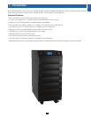
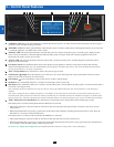
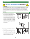
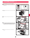
Note: Individual models may vary from diagrams. Unit shown with front bezels removed.
Levelers:• The levelers provide long-term support for the UPS system.
Casters:• The casters are designed for small position adjustments within the final installation location only; they are not designed for moving
the UPS system over longer distances. The casters are not designed to provide long-term support for the UPS system after final installation.
Use the levelers to provide long-term support.
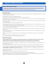
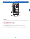
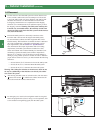
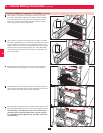
Accessory Slot:• Remove the cover panel to install a Tripp Lite SNMPWEBCARD accessory. The SNMPWEBCARD accessory provides an
Ethernet interface for the UPS system and enables remote monitoring and control via SNMP, Web browser or telnet. Visit www.tripplite.com
for more information about the SNMPWEBCARD accessory.
RS-232 Serial Communications Port:• This DB9 port connects the UPS system to compatible workstations or servers, enabling automatic
shutdown during extended blackouts and monitoring of operating and power conditions.
Parallel Configuration Port:• This DB9 port connects the UPS system to another UPS system of identical type and capacity for use in a
parallel redundancy (1+1) configuration. See Section 7 – Wiring and Section 8 – Operating Modes for more information.
Input Dry Contact Interface:• This interface receives dry contact signals that allow the UPS system to receive commands and monitor
external battery conditions. See Section 11 - Communications for more information.
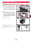
Output Dry Contact Interface:• This interface allows the UPS system to send information via dry contact communications. See Section 11 –
Communications for more information.
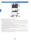
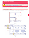
Internal Battery Circuit Breaker Switch (SU20KX and SU40KX only):• Controls the input/output power of the UPS system’s internal
batteries.
Terminal Block Cover:• Remove the terminal block cover to access the UPS system’s input, bypass input, external battery cabinet, output and
grounding connection terminals. Wiring conduits pass through the circular knockouts in the terminal block cover. See Section 7 – Wiring for
more information, including a detailed diagram of the terminal block.
H
I
J
K
L
M
N
O
P
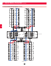
4 – Front and Rear Panel Features (continued)
SU40KX shown (rear)