


1
5
9
3
7
11
2
6
10
4
8
12
13
14
1
2
3
4
A
Output
Output
Output
Manual
Bypass
Manual
Bypass
Manual
Bypass
Bypass
Input
Bypass
Input
Bypass
Input
Main
Input
Main
Input
Main
Input
Q1
Q3
Q2Q4
5
A
6
Q4 Q3
B
31
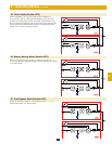
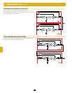
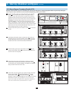
9 – Start-Up, Shutdown and Bypass (continued)
9-10 Manual Bypass Procedure (Parallel UPS)
Warning: When the UPS system is in manual bypass, the inverter shuts down. Connected equipment loads are powered by the bypass
(reserve) power source and will not receive battery backup during a utility power failure.
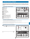
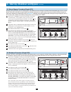
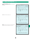
For the first UPS system you wish to shut down, press the OFF •
button
A
for 3 seconds (until you hear a beep), then release
the button. If the other UPS system can support the connected
equipment loads alone, the UPS system that was turned off will
shut down its inverter and its LCD screen will read “LOAD NOT
POWERED”. The other UPS system’s LCD screen will read
“ONLINE MODE”. If the total connected equipment load is too
large to be handled by a single UPS system, both UPS systems
will shut down their inverters and switch to bypass mode, and their
LCD screens will read “ON AUTO BYPASS”. Repeat step 1 for
the second UPS system you wish to shut down.
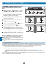
Switch off the main input circuit breaker switch •
Q1
of each UPS
system.
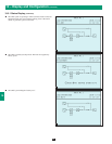
Confirm that both UPS systems are shut down, then switch on •
the manual bypass input circuit breaker switch
Q3
of each UPS
system. The bypass (reserve) power source will power the loads
and the LCD screen will read “ON MANUAL BYPASS”.
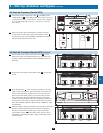
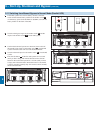
Switch off the bypass input circuit breaker switch •
Q2
and the
output circuit breaker switch
Q4
of each UPS system. The LCD
screen will turn off completely.
1
2
3
4
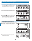
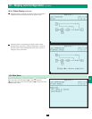
If the UPS systems have external battery cabinets connected, •
switch off the external battery cabinet circuit breaker switch
A
of each battery pack. On the SU20KX or SU40KX, turn OFF the
battery breaker on the back of the UPS.
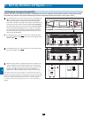
In this mode, only the manual bypass path (including the manual •
bypass circuit breaker
Q3
), the load terminals of the output
circuit breaker switch
Q4
and the terminal block
B
contain
hazardous voltage, allowing qualified service personnel to perform
maintenance or repair. Note: Qualified service personnel may
prefer to de-energize the UPS systems completely, depending on
local codes and the nature of the maintenance or repair.
5
6