


1
5
9
3
7
11
2
6
10
4
8
12
13
14
P1
P2
56
11 – Communications (continued)
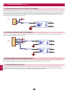
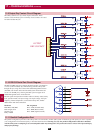
11-4 Remote Emergency Power Off (EPO) Circuit Diagram
The Remote Emergency Power Off (EPO) input connection (P1) allows you to connect the UPS system to your facility’s EPO circuit. Connecting
the UPS system to the EPO circuit enables remote emergency shutdown of the UPS system’s output. Connect EPO input to a user-supplied remote
switch, following the circuit diagram below. This contact is normally open. User supplied REPO button must be latching type and in a normally
closed position. When opened, the UPS goes to bypass. The inverter must then be restarted by pressing the ON button to return to on-line mode.
Contact rated for 12V DC minimum, 0.1A (nominal).
11-5 Auxiliary Dry Contact Input Circuit Diagram
The auxiliary dry contact input connections (P2) allow the UPS system to receive external signals. These contacts are normally open. External
contacts rated for 12V DC minimum, 0.1A (nominal).
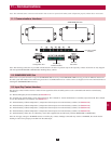
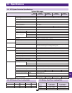
11-6 External Battery Cabinet Temperature Inputs
The external battery cabinet temperature input connections (P3, P4, P5, P6) allow the UPS system to receive signals from an optional accessory
that monitors the temperature of external battery cabinets. Visit www.tripplite.com/support for more information.
11-7 External Battery Status Input
The external battery cabinet status input connection (P7) allows the UPS system to receive external battery cabinet status signals through an
optional cable. Pin 1 = +12V; Pin 2 = detection cable connected; Pin 3 = battery cabinet breaker status (signal active= breaker on; signal inactive =
off); Pin 4 = reserved; Pin 5 = reference voltage. Visit www.tripplite.com/support for more information.