12
5. Hold the lower cover to lift up the top cover open levers to separate the lower
inner cover and the lower cover.
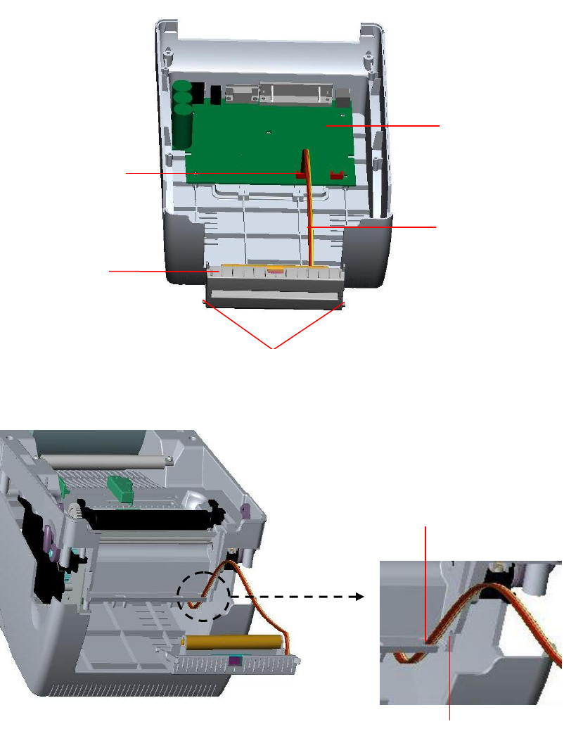
6. Arrange the cable through the bezel. Connect the peel-off panel cable to the
5-pin socket on printer PCB.
Fig. 14 Connect peel-off sensor cable to main board
Fig. 15 Peel-off sensor cable installation
7. Insert the peel-off tenons into the lower inner cover mortises until tenons snap
Peel-off
panel
Peel-off panel
Cable
5-pin Socket
PCB
Tenon
Bezel
Mortise


