http://www.tyan.com
16
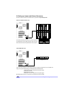
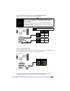
2.6-I. Soft Power Connector
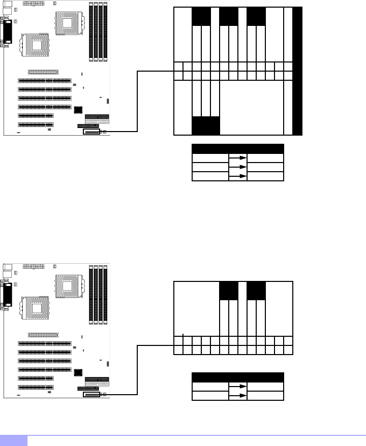
The soft power connector is part of jumper block J12 (pins 13 and 15). This board uses the chipset for
power management, including turning on and off the system. If the power button function option in the
BIOS Power Management menu is set to “On/Off” (which is the default), pressing the power button once
after the BIOS has booted up will turn the system on and off. If the power button function is set to Sus-
pend, pressing the power button once will wake up the system or send it to Suspend mode. In this case,
you cannot turn the system off unless you shut down through the Windows operating system or you hold
the power button down for four seconds (BIOS-dependent feature).
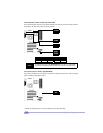
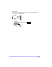
2.6-J. Hardware Reset Switch Connector Installation
The reset switch on your chassis case provides you with the Hardware Reset function, which is the same
as power on/off, except that the system will immediately execute a cold start after the reset button is
pushed. The reset switch needs to be connected to jumper block J12 (pins 7 and 9).
9
GND
SWITCH
7
8101214
11131517
1618
19
20
21
22
23
24
25
26
53
46
1
2
RST
SW
PWR
SW
GND
SWITCH
9
HDD LED
GND
SWITCH
7
8101214
11131517
1618
19
20
21
22
23
24
25
26
53
46
1
2
VCC GND
RST
SW
PWR
SW
GND
SWITCH
SLP
SW
GND
SWITCH
PWR
LED
VCC
no connect
GND
Abbreviations
PWR Power
RST Reset
Abbreviations
ResetRST
PWR Power
SLP Sleep


