


Wireless Access Point Model 0-1591700-x User Manual Page 8 of 33
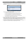
Access Point Ports
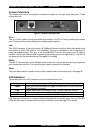
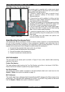
The access point has all the physical connections located on the right hand side panel. These
connections are:-
Figure 1 - Access Point Side Panel
DC In
This is a 3.5mm coaxial format jack socket that accepts +12v DC for locally powering the access
point. Ensure that the correct polarity and voltage range is applied.
LAN
This RJ-45 connector is the auto-sensing 10/100Mbps Ethernet circuit that will be connected to the
local switch or other LAN element. For installation, this port is connected to the configuring PC
using the supplied cable. This port is not Auto-MDI/MDI-X and so the correct type of cable is
needed. This port can also be used for powering the access point by the application of +48v DC on
the spare pairs of the structured wiring. See page 32 for details.
RS232
This 9W D-Type connector is the 9600bps serial console link that can be used during configuration
and maintenance activities. The console system uses a command line interface.
Reset
This push-button switch is used to force a factory default reset of the access point. See page 32.
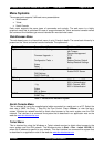
LED Indicators
The access point has 4 LED indicators on the front surface of the unit.
Indicator Function
Power
Lights when there is suitable DC power on either the DC In port or on the
RJ-45 Ethernet LAN cable.
LAN
Flashes when data is transmitted on the 10/100M Ethernet LAN port
A
Flashes when data is transmitted on the 802.11a band radio
B/G
Flashes when data is transmitted on the 802.11b/g band radio
Note that even if there are no wireless clients associated with the access point, the A and the B/G
LEDs will flash when the access point transmits a beacon frame. See page 23 for details.
PL0356 ©2003TycoElectronics Issue 1