


between end nodes. In addition, you should make sure that your network
topology contains no data path loops. Between any two ends nodes, there
should be only one active cabling path at any time. Data path loops will cause
broadcast storms that will severely impact your network performance.
Diagnosing LED Indicators
The Switch can be easily monitored through panel indicators to assist in
identifying problems, which describes common problems you may encounter
and where you can find possible solutions.
If the power indicator does turn on when the power cord is plugged in, you
may have a problem with power outlet, or power cord. However, if the Switch
powers off after running for a while check for loose power connections, power
losses or surges at power outlet. IF you still cannot resolve the problem,
contact your local dealer for assistance.
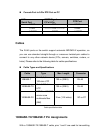
Cabling
RJ-45 ports: use unshielded twisted-pair (UTP) or shield twisted-pair ( STP )
cable for RJ-45 connections: 100_ Category 3, 4 or 5 cable for 10Mbps
connections or 100_ Cat-5 or Cat-5e cable for 100Mbps connections. Also be
sure that the length of any twisted-pair connection does not exceed 100
meters (328 feet). Gigabit port should use Cat-5e or cat-6 cable for 1000Mbps
connections. The length does not exceed 100 meters. For more information
please refer to Appendix section.