


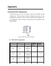

data while pins 3 and 6 are used for receiving data.
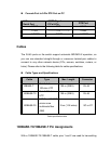
RJ-45 Pin Assignments
Pin Number Assignment
1 Tx+
2 Tx-
3 Rx+
6 Rx-
Note: “+” and “-” signs represent the polarity of the wires that make up each
wire pair.
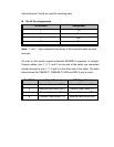
All ports on this switch support automatic MDI/MDI-X operation. In straight-
through cables, pins 1, 2, 3, and 6, at one end of the cable, are connected
straight through to pins 1, 2, 3 and 6 at the other end of the cable. The table
below shows the 10BASE-T/ 100BASE-TX MDI and MDI-X port pin outs:
Pin MDI-X Signal Name MDI Signal Name
1 Receive Data plus (RD+) Transmit Data plus (TD+)
2 Receive Data minus (RD-) Transmit Data minus (TD-)
3 Transmit Data plus (TD+) Receive Data plus (RD+)
6 Transmit Data minus (TD-) Receive Data minus (RD-)