5
4000 Installation
2.3 Grounding the Equipment
Warning! The ATT must be grounded before communication and power connections are made.
An external grounding lug is provided on the ATT. A connection from the ground lug to earth ground must be made
before any other wiring connections are made.
Note! For adequate/proper operation of the ATT lightning arrestor, a ground strap must be attached to the ATT. Grounding
through mounting kits or pipe coupling is not adequate.
Note! Properly seal all ports to prevent moisture or other contamination from entering the wiring compartment.
2.4 Wiring
Connections should be made in a conventional manner according to local or plant electric codes.
Warning! Explosion-proof seals must be installed in all wiring entries. Any unused entries must be plugged with pipe plugs and
secured with Loctite®, or equivalent.
2.4.1 ATT Wiring
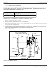
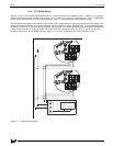
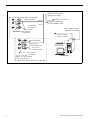
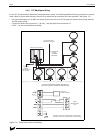
Wiring the ATT is described in the following paragraphs. The wiring diagram provided in Figure 2-3 on page 6 should
be used in conjunction with these wiring instructions.
2.4.2 Wiring Preparation
Remove the two thread protectors from the 1/2-inch NPT conduit entries at the top and bottom of the ATT. Remove
the rear cover from the ATT housing.
2.4.3 Connecting Input Power
Warning! When connecting DC power leads to the ATT, make certain that power is OFF.
The ATT operates on a 24-48 volts DC power source. The input power connection to the ATT is accomplished in the
following manner.
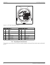
Connect the positive side of the power supply to terminal 10, B+, and the negative side to terminal 9, B-, of the
terminal block assembly. See Figure 2-3 on page 6.


