


VXI Technology, Inc.
12 EX7000 Series Introduction
F
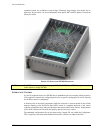
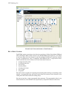
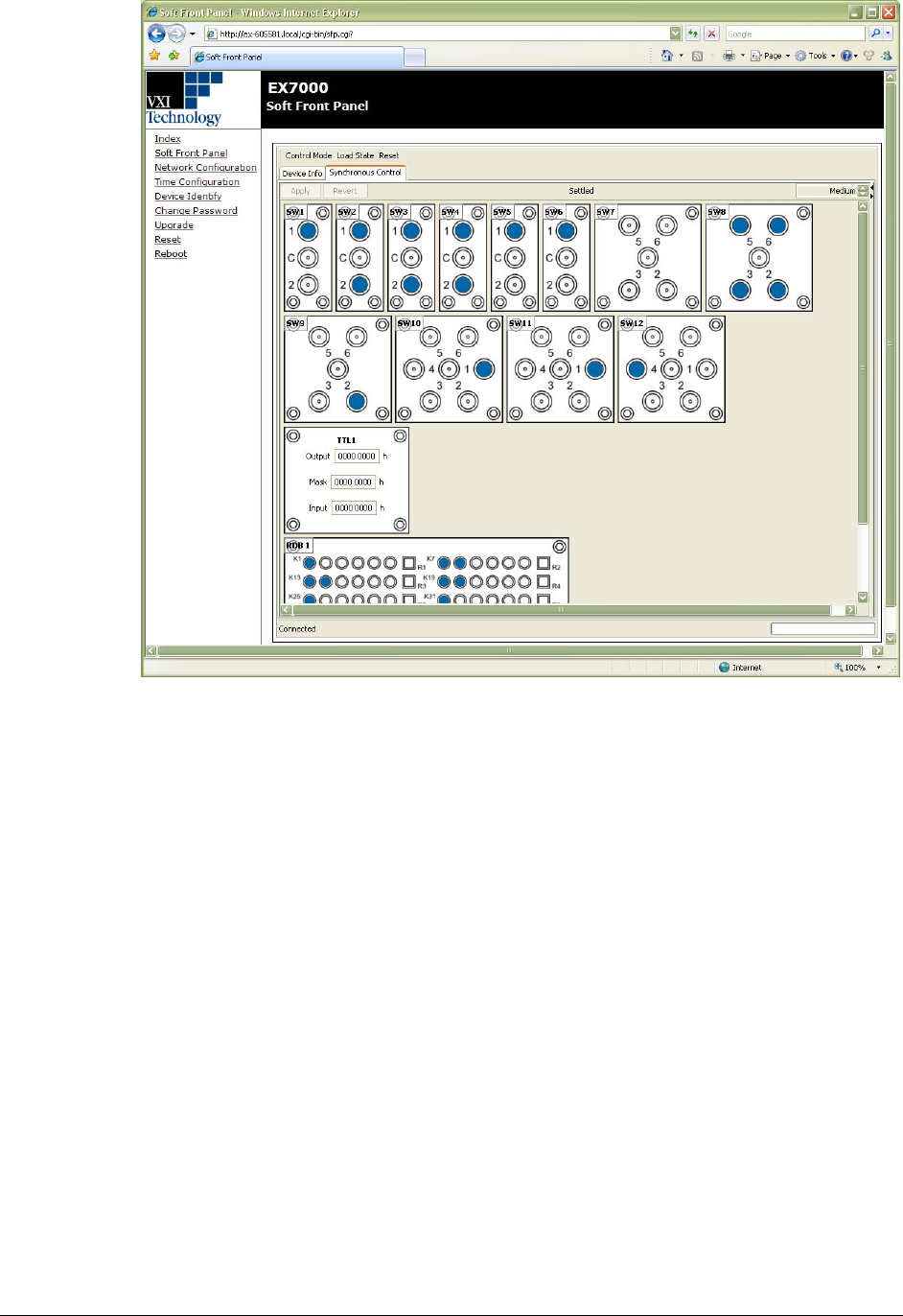
IGURE 1-4: JAVA-BASED GRAPHICAL USER INTERFACE
RELAY DRIVE CONTROL
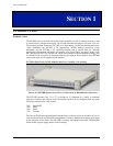
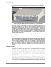
The EX7000 contains a proprietary circuit board set consisting of a Relay Driver Board (RDB)and
LXI LAN Interface Board, which is known as the EX7000-OEM when supplied as a set without
an enclosure. They have been designed to provide maximum flexibility for controlling virtually
any type of RF/microwave relay or component. Each RDB provides 72 high-current drivers,
which are divided into twelve sections of six lines. Each section consists of:
• six high-current drive lines
• six indicator/status bits
• one reset line
• four relay ID bits
• one relay power input
• one 5 V input
• one ground
Each driver board is capable of recognizing and controlling either latching or non-latching switch
modules. A programmable delay (per driver board) dictates the amount of time allocated to relay
settling times and current cutoffs (for latching relays).
Each driver board has a single programmable delay parameter. The programmable delay for any
board should be set to the maximum value required by any component connected to that board.