


www.vxitech.com
EX7000 Series Basic Operation 21
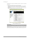
When enabled as an output, each channel also has the ability to generate a 1 µs pulse upon
command. An example application of this pulse is to use the EX7000 to externally trigger another
piece of test equipment. The specific operation of the pulse depends on the static level
programmed for that channel. When a channel is programmed with a static level of high, the pulse
will be low-going. When a channel is programmed with a static level of low, the pulse will be
high-going. Each pulse generation requires a separate command.
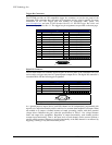
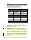
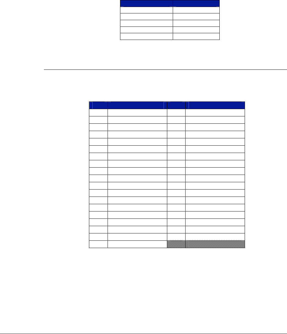
The electrical specifications for the digital I/O port are provided in
Table 3-1. Particular note
should be given to the V
INPUT
specification of -0.5 V to 5.5 V. Exceeding that value with an
external voltage source, even through a resistance, could permanently damage the EX7000.
Characteristic Value
V
INPUT
-0.5 V to 5.5 V
V
IH
2 V min
V
IL
0.8 V max
V
OH
(I
OH
= -32 mA) 2 V min
V
OL
(I
OL
= 64 mA) 0.55 V max
TABLE 3-1: DIGITAL I/O PORT ELECTRICAL SPECIFICATIONS
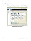
General Purpose I/O
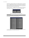
The EX72SF features an additional 32-bit general purpose TTL I/O port. This is in additional to
the internal 72-channel relay drivers and the 8-bit digital I/O described above. The following are
the pin assignments for the rear-mounted 37-pin D-sub connector:
Pin Signal Pin Signal
1 GND 20 PIO-PORT0
2 PIO-PORT1 21 PIO-PORT2
3 PIO-PORT3 22 PIO-PORT4
4 PIO-PORT5 23 PIO-PORT6
5 PIO-PORT7 24 PIO-PORT8
6 PIO-PORT9 25 PIO-PORT10
7 PIO-PORT11 26 PIO-PORT12
8 PIO-PORT13 27 PIO-PORT14
9 PIO-PORT15 28 GND
10 +5 V 29 GND
11 PIO-PORT16 30 PIO-PORT17
12 PIO-PORT18 31 PIO-PORT19
13 PIO-PORT20 32 PIO-PORT21
14 PIO-PORT22 33 PIO-PORT23
15 PIO-PORT24 34 PIO-PORT25
16 PIO-PORT26 35 PIO-PORT27
17 PIO-PORT28 36 PIO-PORT29
18 PIO-PORT30 37 PIO-PORT31
19 GND
A current limited supply of +5 V is provided on pin 10. An internal, resettable fuse is provided to
protect 200 mA against excessive current flow and short circuits.