


VXI Technology, Inc.
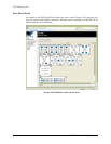
36 EX7000 Series Web Page Operation
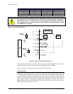
RDBs can either be commanded one board at a time or several RDBs may be commanded
simultaneously. The RDB has 72 relay control drive lines capable of sinking 200 mA and twelve
very high-current reset lines capable of sinking 800 mA. They are divided into three banks, each
can be powered separately. Each bank consists of four 20-pin connectors. Each connectors
consists of:
• six high-current drive lines
• six indicator/status bits
• one very high-current reset line
• four relay ID bits
• one relay power input
• one 5 V input
• one ground
NOTE All devices connected to a particular bank (i.e. group of four connectors) must be of the same
type: continuous or latching. Mixing of different type may result in erratic behavior and damage to
overall system.
OPEN-COLLECTOR VS. TTL DRIVE LINES
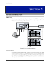
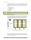
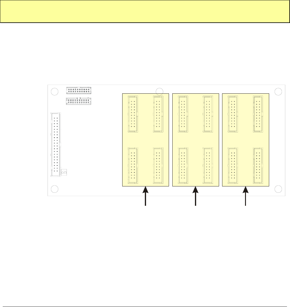
The EX7300 and EX7400 relay drive connectors reside on a (RDBs) that are partitioned into three
banks: J2 through J5 constitute bank 0, J6 through J10 bank 1, and J11 through J14 bank 2.
Although a single RDB may contain both latching and non-latching devices, the banks may only
contain one type of device. For example, if J2, J3, and J4 are connected to non-latching devices, J5
may only contain a non-latching relay. A latching relay could, however, be installed in J6.
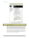
J13
J12
Some connectors have been removed for clarity.
Bank 0Bank 1Bank 2
Relay Driver Board (RDB)
J9
J8
J7
J6
J5
J4
J11
J10
J3
J2
F
IGURE 5-2: RELAY DRIVE CONNECTOR BANKS
Additionally, the RDB of the EX7300 and EX7400 may have varying quantities of open-collector
and TTL drive lines, depending on the model ordered. This property is linked to the relay drive
connector banks, as illustrated in
Figure 5-2. The following table indicates how banks are used
according the part number assigned.