


3.0 INTERFACES
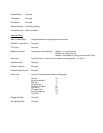
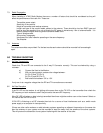
3.1 Communication Port 9 Way D Type Connector RS232/RS485
1 ALARM CONTACT OUTPUT
6 ALARM CONTACT OUTPUT
2 RS232 RD RECEIVE DATA INPUT
7 -VE RS485 INPUT/OUTPUT
3 RS232 TD TRANSMIT DATA OUTPUT
8 CTSI OUTPUT
4 NU
9 +VE RS485 INPUT/OUTPUT
5 0V INPUT
PIN 1 AL1 Voltage free, normally open contact
PIN 2 RD RS232 Receive serial data from host
PIN 3 TD RS232 Transmit serial data to host.
PIN 4 NU Not Used
PIN 5 OV 0V common for host.
PIN 6 AL2 Voltage free, normally open contact
PIN 7 –VE RS485 Bi-directional data.
PIN 8 CTS Brought low by the modem when a RF carrier is detected or the receiver buffer memory is full.
This can be connected to RTS on the host to inhibit data from the host in duplex operations.
PIN 9 +VE RS485 Bi-directional data.
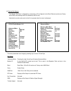
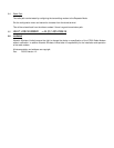
3.2 Service Port 9 Way D Type Connector RS232/RS485
1 NOT USED
6 CONFIGURATION MODE INPUT
2 RS232 RD RECEIVE DATA INPUT
7 -VE RS485 INPUT/OUTPUT
3 RS232 TD TRANSMIT DATA OUTPUT
8 NOT USED
4 NU
9 +VE RS485 INPUT/OUTPUT
5 0V INPUT
PIN 1 NU Not Used
PIN 2 RD RS232 Receive serial data from host
PIN 3 TD RS232 Transmit serial data to host.
PIN 4 NU Not Used
PIN 5 OV 0V common for host.
PIN 6 CON Configuration input. Connecting 0V to this input will send the configuration menu to the host
when the power is applied. It is left open circuit for normal operation.
PIN 7 –VE RS485 Bi-directional data.
PIN 8 NU Not Used.
PIN 9 +VE RS485 Bi-directional data.