


3.3 LED Indicators
Eight LED’s on the front of the modem indicate the following states:
Transmit Data 1 Green On when modem 1 is transmitting data.
Receive Data1 Green On when a RF carrier of greater than 0.9uV is detected
PSU 1 Red On when Modem 1 power supply is good.
Fail 1 Red On when a fault is detected in Modem 1
Data 2 Green On when modem 2 is transmitting data.
Receive Data 2 Green On when a RF carrier of greater than 0.9uV is detected
PSU 2 Red On when Modem 2 power supply is good.
Fail 2 Red On when a fault is detected in Modem 2
3.4 Fuses
Fuse 1 1 Amp Fuse for modem 1 PSU
Fuse 2 1 Amp Fuse for modem 1 PSU
3.5 Program Switch
Three way switch for changing the parameters of both modem 1 and modem 2.
Central Run
Right Program modem 1
Left Program modem 2
3.6 Alarm Reset
Resets alarm states
3.7 Antenna Connections
Two 50 ohm, N-Type Sockets.
Antenna 1 Socket for Antenna 1
Antenna 2 Socket for Antenna 2
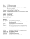
3.8 Power Supply
Three pin plug for 240V mains power supply is
4.0 OPERATION
When power is applied to the Dual Redundant Base Station all the monitored parameters are checked along
with the LED’s. If no faults are found modem 1 is enabled. The Duty Cycle Timer is enabled and this then cycles
the two modems according to the time set in the service menu. ( 1 to 48 Hours)
If a fault is detected in the operational modem then the Fault LED will light, the Fault Relay will energise, an
error code will be set in the service menu and the alternative modem will be selected.
A transmission is started by sending data to RD (pin 2) on the serial communication port. The operational radio
modem places this data in the transmitter buffer memory while it checks to see if the RF. channel is free. If it is