


2-2
IPS-800/IPS-1600 Series - User’s Guide
➂
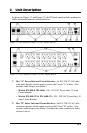
Bus "A" Switched Plugs and Plug Indicators: AC Outlets that can be
switched On, Off or rebooted in response to user commands.
• IPS-800: Four 100-120 VAC, NEMA 5-15 Outlets with indicator
lights. 15 Amps Total Load.
• IPS-1600: Eight 100-120 VAC, NEMA 5-15 Outlets with indicator
lights. 15 Amps Total Load.
• IPS-800-CE: Four 208-240 VAC, IEC-320-C13 Outlets with indicator
lights. 10 Amps Total Load.
• IPC-1600-CE: Eight 208-240 VAC, IEC-320-C13 Outlets with
indicator lights. 10 Amps Total Load.
➃
Bus "B" Switched Plugs and Plug Indicators: AC Outlets that can be
switched On, Off or rebooted in response to user commands. Includes
same components listed in item 3 above.
➄
Default Button: This button can be used to either reset the unit to default
parameters or manually toggle all plugs On or Off:
• Default Parameters: With the Master I/O Switch (Master Power
Switch) set in the Off position, press and hold the Default Button, then
set the Master I/O Switch in the On position and release the Default
Button. All menu defined parameters will be reset to default values.
• Manual Plug Toggle: Press the Default Button and hold it down for
three seconds. All IPS power outlets will be toggled On or Off.
Note: If desired, the Default Button’s manual plug control
capabilities can also be disabled as described in Section 5.3.1.
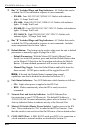
➅
Unit Status Indicators: Two LED Indicators which function as follows:
• ON: Lights when power is applied to the IPS Unit.
• RDY: Flashes continuously when the IPS is ready to recieve
commands.
➆
Network Port and Activity Indicator: An RJ45 Ethernet Port
for connection to your TCP/IP network. The default IP Address is
192.168.168.168, for more information, please refer to Section 5.3.4. The
Activity Indicator flashes to indicate activity at the Network Port.
➇
Master I/O Switch (Master Power Switch): Applies power to the IPS
Unit. This switch must be "On" in order for the IPS to function. Note
that this switch is not used to set the On/Off status of the switched outlets.
➈
COM / RS232 Port: A DB9, RS232 serial port (DTE), for connection to
a local terminal or external modem, as described in Section 4.3.