


tion from this possibility or sited with care in the shelter of some other
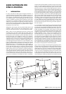
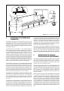
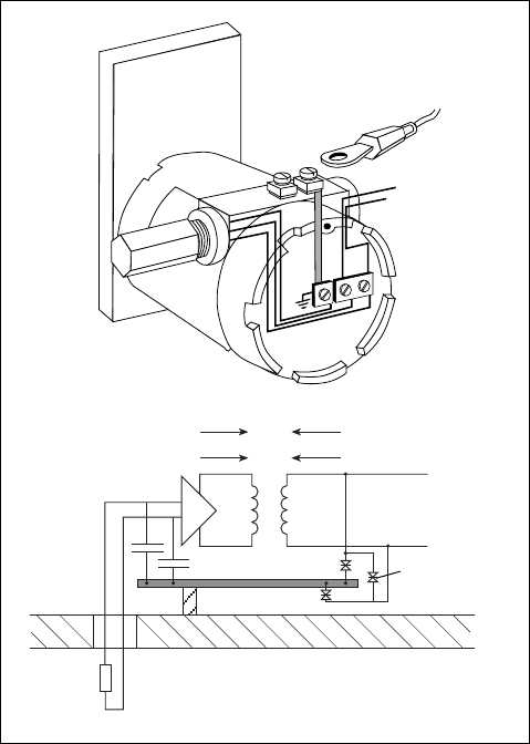
protrusion. The diagram shows a two wire 4 to 20 milliamp transmitter
with internal isolation fed from a galvanic isolator. To establish the
order of the problem some assumptions are made which cannot be
fully justified but are believed to be reasonable. These are:
a) The tank has an inductance of 0.1µH/metre and is 10 metres high
before reaching the equipotential plane of the plant.
b) The potential equalisation system has a similar low inductance of
0.1µH/metre and the tank is situated some 500 metres from the
control room.
c) Lightning strikes the tank, and the strike is 100kA rising linearly in
10 microseconds. Some 10kA is assumed to flow through the po-
tential equalising bond to the control room distribution centre trans-
former.
With these assumptions the transient peak volts across the tank is 10kV
and the voltage across the potential equalising network is 50kV. The
resultant 60kV potential difference would be divided across the isola-
tion within the interface and the isolation within the transmitter with a
high probability that both would break down.
This example is used to illustrate the remainder of this document. In
practice all specific installations will differ in detail from this example
but the general principles are illustrated by this analysis. Usually a
document of conformity for the intrinsically safe system in accordance
with EN50039 should be generated for the specific system. The com-
bination of MTL Instruments Ltd and Telematic Ltd is particularly suited
to giving assistance in creating such documentation, should help be
required.
2 INTRINSIC SAFETY REQUIREMENTS
FOR EARTHING AND BONDING
Usually instrumentation introduced into a Zone 0 is intrinsically-safe to
the ia requirements and is nearly always ia IIC T4 certified by some
appropriate organisation. If this simplifying assumption is made then
certain aspects of intrinsic safety practice need to be examined with
this application in mind.
In the IEC draft code of practice a strong preference for using galvani-
cally isolated interfaces for Zone 0 is expressed. The arguments for
galvanic isolation have always been strongly advocated within Ger-
many and France and are based on the assumption that galvanically
isolated circuits are less susceptible to earth faults and potential differ-
ences between earths than shunt-diode safety barriers. There are liter-
ally millions of circuits using shunt-diode safety barriers and although
there have been a number of operational problems, there is no indica-
tion that any safety problem has arisen from their use and hence prob-
ably the arguments are theoretically correct but may not be practically
significant. However the economic difference between shunt-diode safety
barriers and isolators is not significant in this type of installation and if
necessary high accuracy transfer can usually be achieved using dig-
ital signals. Although an acceptable solution using shunt-diode safety
barriers can be achieved, this analysis proceeds on the assumption
that isolated interfaces will be used if only to avoid the distraction of
any argument resulting from the use of shunt-diode safety barriers.
It is usual to require that intrinsically safe circuits are fully floating or
earthed at one point only. The reason for this requirement is to prevent
significant circulating currents flowing within the circuit due to poten-
tial differences within the plant. The problem is not so much that there
is a significant safety risk but that it is difficult to certify a system with
unspecified currents. In practice the safety analysis carried out with
multiple earth faults is based on the assumption that all earths are at
the same potential and interconnected by zero impedance. Since the
single earth philosophy is largely compatible with the low frequency
interference avoidance practices in instrumentation this has not been
challenged until recently. The increased awareness arising from the
EMC directive of the effects of high frequency interference has led to
the greater use of decoupling capacitors on input circuits which are a
form of multiple earthing. This is recognised in both the apparatus
standard and the code of practice, the latter permitting a total capaci-
tance of 10nF in any one circuit.
When the apparatus standard was being written the question of the
quality of the insulation of the circuit from earth was discussed. It was
decided that except where the intrinsic safety was critically dependent
e.g. where a current limiting resistor could be short circuited, then the
creepage and clearance requirements should be waived but that the
measure of insulation adequacy was a 500 volt insulation test. This
has led to occasional problems e.g. strain gauges, but in general has
not caused problems. It was not thought that circuits would be sub-
jected to 500 volts in the hazardous areas, if they are, then they are no
longer intrinsically safe. [Note - Using 20 microjoules as the ignition
energy of hydrogen, the permissible capacitance associated with 707
volts is 80 picofarads and the safe voltage corresponding to the per-
mitted 10 nanofarads is 63 volts]. The subsequent analysis therefore
ignores the 500 volt insulation test requirement and concentrates on
producing a solution which reduces the voltages applied to the Zone 0
in transient conditions to an acceptably safe level.
3 CERTIFICATION OF SURGE SUPPRESSORS
Usually, surge suppressor circuits can be classified as “simple appara-
tus” using any of the available definitions. Fortunately the requirements
of simple apparatus have been more clearly defined in the second
edition of EN50020 (reproduced in Appendix 2) and hence due al-
lowance for the small inductors sometimes used can now be made.
It is normal practice to have “simple apparatus” certified by an appro-
priate body such as BASEEFA if they are frequently used in intrinsically
safe circuits. Although not strictly essential such third party certification
gives additional comfort to the end user and makes the marketing of
the product easier. It is important however to recognise that the certifi-
cation relates only to the effect the surge suppression device has on the
intrinsic safety of the circuit when the circuit is not affected by lightning
transients. There are no requirements in the apparatus standards relat-
ing to the performance of surge suppressors. Although BASEEFA do
satisfy themselves that the product they are certifying is not useless they
are not responsible for its performance during a transient surge, nor is
anyone able to claim that the circuit is intrinsically safe during the brief
time it is affected by the lightning surge. The full implications of the
recent “ATEX” directive with respect to surge suppressors has not yet
been pursued, but may lead to some additional testing requirements.
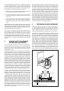
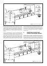
Figure 2 Surge suppresion of the transmitter
Tank shell
L
1
L
2
60V
60V
60V
Instrument
housing
300V
2µS
60V
+
–
TP48
2