


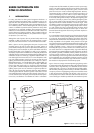
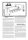
The system should be designed so that when the surge current is di-
verted the voltage drop across the bonding conductor does not create
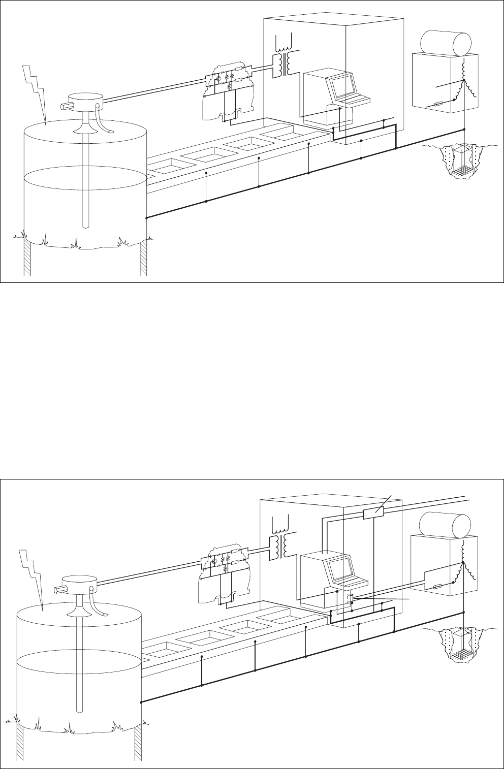
a large voltage across the isolator. Figure 4 gives an illustration of a
satisfactory system. With the currents and distances indicated the iso-
lator is still subjected to a 1.5kV pulse and hence the importance of
keeping the interconnection as short as possible cannot be over em-
phasised.
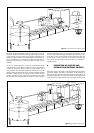
The use of a second suppressor on the circuit means that the intrinsi-
cally safe system is now indirectly bonded at two points. The sequence
in which the suppressors begin to conduct is quite complex since it
does depend on how the potential difference between the two earths
develops. The sustained situation which is the least desirable is that the
transmitter protector requires 60 volts to conduct and the computer
protector 30 volts to conduct. Hence there would need to be at least
90 volts between the two earths before a significant current could flow
within the intrinsically safe circuit. During this short time the circuit is
not intrinsically safe but the equipment at either end of the line is oper-
ating within its rating. Any hazard which does exist is in the cable and
is in the Zone 1, or Zone 2 location. It is a smaller hazard than that
which would exist without the protection and hence is a desirable ac-
ceptable solution.
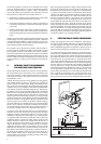
6 PROTECTION OF SUPPLIES AND
SIGNALS FROM EXTERNAL SOURCES
If the mains supply to the system is subject to lightning surges then the
operational integrity and safety of the system can be adversely af-
fected. An obvious invasion route for the intrinsically safe system is via
the isolator supply which is derived either directly or indirectly from the
supply. The intrinsic safety certification process assumes that the power
1kA (10µS)
15m
15µH
1.5kV
Data link
Mains Filter
suppressor
Signal Suppressor
Mains supply
4
Figure 4 Intrinsically safe circuit fully protected
Figure 5 Adequately protected system