


4 PROTECTION OF THE SENSOR AND
TRANSMITTER
The problem of surge protection of the transmitter and sensor is rela-
tively easy to solve since it is only necessary to prevent significant
voltage differences so as to avoid ignition capable sparks. This can be
achieved by using a combination of surge limiting devices, which ef-
fectively control the voltage between the signal wires and with respect
to the adjacent structure.
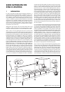
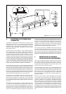
A practical solution to this problem is to use a Telematic TP48 (see
figure 2) which contains the necessary parallel surge components in
an encapsulated block within a stainless steel hexagon bar which can
be screwed into the unused cable entry of the transmitter. To achieve
suppression against the expected transients it is necessary to use a
combination of gas discharge tubes and solid state devices. With the
usual test waveform this combination restricts the transient voltage be-
tween the circuit and structure to 300 volts which then falls to 60V after
two microseconds and the voltage between the signal lines to 60V. It is
a matter of some debate as to what transient voltages would be antici-
pated on a practical installation with protection but they would not
exceed 150V and almost certainly would be considerably less.
To be effective the surge suppressor must be adequately bonded to the
structure. Almost all transmitters contained within metallic enclosures
have both internal and external bonding connections which can be
utilised to ensure adequate bonding. The need for the external bond is
reduced if the mounting of the transmitters ensures an effective bond.
but if there is any doubt a substantial bond should be used. The size of
the bond is largely determined by the need to be mechanically robust.
A flat short braid with suitable tags has much to commend it.
This suppression circuit produces in the worst case condition a short
150V pulse across the transmitter isolation and a longer 60V pulse,
both of which the isolation will normally reject. Any small transient
which is fed by the transformer capacitance to the sensor circuit would
be absorbed by the high frequency input filter capacitors of the sensor
input circuit.
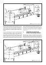
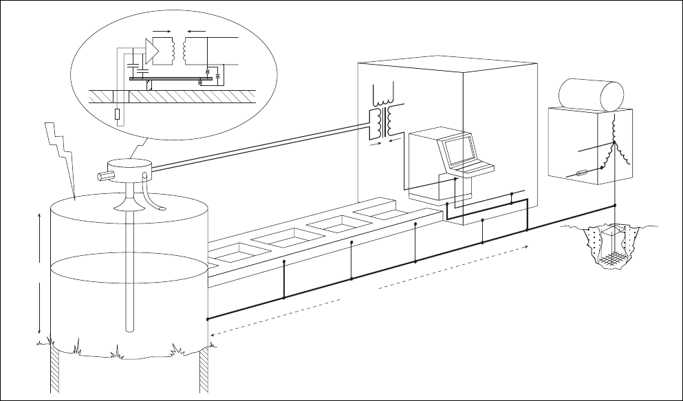
The results of fitting surge suppression on the transmitter therefore en-
sures that there is an adequate level of protection for the sensor and
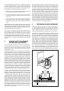
transmitter. However removing the potential difference from the trans-
mitter transfers the whole of the potential difference to the isolator as
illustrated in Figure 3. Typically an intrinsically safe isolator will with-
stand an occasional 5kV transient (the components are routinely tested
at 1.5kV rms) but damage would be expected at 60kV. The usual result
of this failure would be damage to the computer interface which would
have both cost and operational safety implications. In non hazardous
locations it is not unusual for the loss of individual transmitters to be
accepted as sacrificial but to protect the computer interface so that the
possibility of more complex interacting faults is reduced, and the pos-
sibility of the total system being shut down is removed.
The suppressor discussed has a BASEEFA certificate which permits its
use in conventional intrinsically safe circuits [it is also Ex d certified].
The level of protection offered has been carefully chosen so that all
known two wire transmitters can be adequately protected. The leak-
age currents associated with shunt protection devices are controlled so
that they do not significantly affect the operational accuracy of the loop.
5 PROTECTION OF THE GALVANIC
ISOLATOR AND SAFE-AREA EQUIPMENT
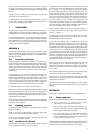
The use of surge suppression between the isolator and the computer
input interface protects the computer interface and the isolators are
then sacrificial. The unspecified damage to the isolators is not however
desirable and the better installation is to protect the isolators on the
hazardous area side as indicated in figure 4.
The standard solution to this problem is to use the SD32X which would
reduce the voltages applied to the isolator to the acceptable levels as
indicated and would not significantly affect the operation of the circuit.
[Note. There is a version of the suppressor which has a replaceable
fuse and isolation link. In this application the fuse it not likely to be
blown hence this alternative should only be used if the isolation link is
thought to be useful].
The SD series has not yet been certified by BASEEFA as being suitable
for connection into intrinsically safe circuits although an application
has been made and hence its acceptability is based on it being simple
apparatus as defined in the second edition of EN50020 [see Appen-
dix B]. It does contain two small inductors which have a combined
inductance of 200 microhenries. However the conventional transmitter
circuit is powered from a 28 volt 300 ohm source which has permitted
cable parameters of 0.13 microfarads and 4.2 millihenries. The per-
mitted length of cable is usually restricted to approximately 600 metres
by the capacitance requirement and hence a marginal reduction of the
permitted inductance to 4 millihenries (equivalent to 4Km) has no ef-
fect.
10kV
TP48
Bonding strap
60V
60kV
50kV
3
Figure 3 System with transmitter only protected