


supply will contain a significant amount of surges but if for any reason
the supply is particularly exposed to invasion from lightning induced
surges then some consideration to suppressing the main supply should
be given.
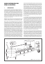
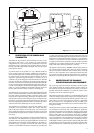
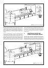
A practical economic solution is to protect the supply input to the com-
puter system as indicated in figure 5.
A similar argument can be made if a data link is made to any remote
location. This is less likely to directly affect the intrinsically safe circuit
but can be very damaging to the computer.
7 CONCLUSION
The solution shown in figure 5 is therefore the best practical solution to
achieve safety for circuits entering Zone 0 where there is a significant
probability of the circuit being influenced by adjacent lightning strikes.
It is probable that this solution is not directly applicable to all installa-
tions but a solution based on a similar analysis is usually achievable.
MTL and Telematic are in an almost unique position to give advice on
this problem and consider that they have the competence to assist in
preparing the relevant documentation.
APPENDIX A
This appendix is comprised of extracts from the draft IEC 79-14 code
of practice of electrical installations in hazardous areas dated October
1994. It may still be modified in detail but it is not probable that the
principles will change.
6.3 Potential equalisation
Potential equalisation is required for installations in hazardous areas.
For TN, TT and IT systems all exposed and extraneous conductive parts
shall be connected to the equipotential bonding system. The bonding
system may include protective conductors, metal conduits, metal cable
sheaths, steel wire armouring and metallic parts of structures, but shall
not include neutral conductors. Connections shall be secure against
self-loosening.
Exposed conductive parts need not be separately connected to the
equipotential bonding system if they are firmly secured to and are in
metallic contact with structural parts or piping which are connected to
the equipotential bonding system. Extraneous conductive parts, which
are not part of the structure or of the electrical installation, need not be
connected to the equipotential bonding system, if there is no danger of
voltage displacement, for example frames of doors or windows.
For additional information see clause 413 of IEC 364-4-41.
Metallic enclosures of intrinsically-safe apparatus need not be connected
to the equipotential bonding system, unless required by the apparatus
documentation. Installations with cathodic protection shall not be con-
nected to the equipotential bonding system unless the system is specifi-
cally designed for this purpose.
NOTE - Potential equalisation between vehicles and fixed installations
may require special arrangements, for example, where insulated flanges
are used to connect pipelines.
6.5 Lightning protection
In the design of electrical installations, steps shall be taken to reduce
the effects of lightning.
NOTE - In the absence of IEC standards on protection against light-
ning, national or other standards should be followed.
Subclause 12.3 gives details of lightning protection requirements for
Ex ‘ia’ apparatus installed in Zone 0.
12.3 Installations for Zone 0
Intrinsically-safe circuits shall be installed in accordance with 12.2 except
where modified by the following special requirements.
In installations with intrinsically-safe circuits for Zone 0 the intrinsically-
safe apparatus and the associated apparatus shall comply with IEC
79-11 category ‘ia’. Associated apparatus with galvanic isolation
between the intrinsically-safe and non-intrinsically-safe circuits is pre-
ferred. Associated apparatus without galvanic isolation may be used
provided the earthing arrangements are in accordance with item 2) of
12.2.4 and any mains powered apparatus connected to the safe area
terminals are isolated from the mains by a double wound transformer,
the primary winding of which is protected by an appropriately rated
fuse of adequate breaking capacity. The circuit (including all simple
components, simple electrical apparatus, intrinsically-safe apparatus,
associated apparatus and the maximum allowable electrical param-
eters of interconnecting cables) shall be of category ‘ia’.
Simple apparatus installed outside the Zone 0 shall be referred to in
the system documentation and shall comply with the requirements on
IEC 79-11, category ‘ia’.
If earthing of the circuit is required for functional reasons the earth
connection shall be made outside the Zone 0 but as close as is reason-
ably practicable to the Zone 0 apparatus.
If part of an intrinsically-safe circuit is installed in Zone 0 such that
apparatus and the associated equipment are at risk of developing
hazardous potential differences within the Zone 0, for example through
the presence of atmospheric electricity, a surge protection device shall
be installed between each non-earth bonded core of the cable and the
local structure as near as is reasonably practicable, preferably within
1 m, to the entrance to the Zone 0. Examples of such locations are
flammable liquid storage tanks, effluent treatment plant and distillation
columns in petrochemical works. A high risk of potential difference
generation is generally associated with a distributed plant and/or ex-
posed apparatus location, and the risk is not alleviated simply by us-
ing underground cables or tank installation.
The surge protection device shall be capable of diverting a minimum
peak discharge current of 10 kA (8/20 µs impulse to IEC 60-1, 10
operations). The connection between the protection device and the
local structure shall have a minimum cross-sectional area equivalent to
4 mm
2
copper.
The spark-over voltage of the surge protection device shall be deter-
mined by the user and an expert for the specific installation.
NOTE - The use of a surge protection device with a spark-over voltage
below 500 V a.c. 50 Hz may require the intrinsically-safe circuit to be
regarded as being earthed.
The cable between the intrinsically-safe apparatus in Zone 0 and the
surge protection device shall be installed such that it is protected from
lightning.
APPENDIX B
Requirements of simple apparatus extracted from EN50020:1994.
5.4 Simple apparatus
The following apparatus shall be considered to be simple apparatus:
a) passive components, e.g. switches, junction boxes,
potentiometer and simple semiconductor devices.
b) source of stored energy with well defined parameters, e.g.
capacitors or inductors, whose values shall be considered when
determining the overall safety of the system.
c) sources of generated energy, e.g. thermocouples and photo-
cells, which do not generate more than 1,5 V, 100 mA and
25 mW. Any inductance or capacitance present in these sources
of energy shall be considered as in b).
Simple apparatus shall conform to all relevant requirements of this stand-
ard but need not be certified and need not comply with clause 12. In
particular the following aspects shall always be considered.
5