


08905107C - 2 -
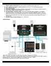
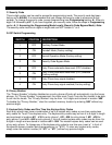
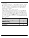
1. Power supply connection. Be sure to use the included power supply only.
2. C.O. / Phone Line Input. If installing without a C.O. line, “*5” must be programmed.
3. Entry Phone Input.
4. Line Out to Phones. Can be connected to an unused line / trunk input on a phone system.
5. Door Strike, Relay Contact Output. N.O., COM, N.O.
6. Doorbell Switch / Auxiliary Input. Connect to a doorbell switch (lighted or non-lighted)
momentary SPST 6-16V bulb. Note: Unit must be in Doorbell Mode (DIP switch 1 ON). Or
uses as an Auxiliary Input, allowing connection to a momentary SPST switch, keyed switch,
postal lock with limit switch, etc. Note: Unit must be in Auxiliary Contact Mode DIP switch 1
must be off.
7. Auxiliary Relay Contact Output. N.C., COM, N.O.
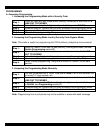
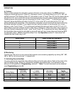
APPLICATION
Note: DIP switch 2 must be ‘on’ (DPC100), DIP switch 1 must be ‘off’ (DCH4)
Note: To provide unique front and back door chimes, the DCH4 must have the AUXILIARY contact
programmed for “Entry Phone Triggered Rind Cadence Activation” (3#60).
See Programming Section B Quick Programming Features.