-5-
CUSTOM EDID CONFIGURATION VIA DIP SWITCHES
Extended display identifi cation data (EDID) is a data structure provided by a display to
describe its capabilities to any source that asks for it. The EDID includes manufacturer
name, product type, timings supported by the display, display size, luminance data, (for
digital displays only) pixel mapping data, supported audio channels and formats. This
information is used by the source to cater its output to resolutions and audio formats that
are supported by the display.
When displays are not properly recognized by HD source equipment, or when custom
display confi gurations are desired, you can manually adjust the EDID parameters to
achieve results using a bank of small switches inside the Xantech Splitter known as DIP
(Dual In-Line Package) switches.
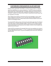
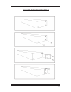
To access the DIP switches, remove all screws from the bottom and sides of the Xantech
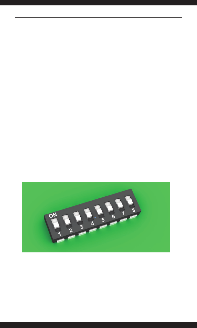
unit’s metal chassis. Carefully slide the unit apart. The bank of 8 DIP switches is located
on the main printed circuit board (PCB). Switches can be moved by a small screwdriver
or other pointed object. Once adjustments are complete, slide the unit back together and
replace all removed screws.
Additional EDID modes beyond the standard built-in modes are available and confi gured
using a combination of DIP switches 1, 2, 5 and 7. Please refer to the following page for a
list of the different EDID modes. The picture immediately below shows what a DIP switch
bank looks like:


