


Release 2.1 25
Section 2. Installation and Configuration
Introduction
To use this product, you must have the following equipment:
• a compatible model of DC output power supply
• IEEE-488 connector and cable
• computer with an IEEE-488 interface card
• Computer-based communications software package
• parallel CANbus cables (to connect power supply for multichannel operation)
The GPIB
or CANbus interface is usually installed in a power supply at the factory.
Your local distributor or service center can also install the interface, especially for
use in a previously-purchased supply already on site. The interface card will be
calibrated and configured with default settings. You will need to configure the supply
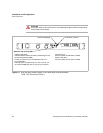
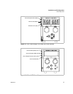
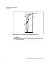
for your system using the “Basic Setup Procedure” on page 31. Refer also to
Figure 2.1, pg. 26, Figure 2.2, pg. 27 and Figure 2.3, pg. 27 for drawings of the front
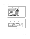
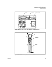
panels. The interface subplate is different for each product. Please check Figure 2.4
to Figure 2.7.
Initial Inspection
On first receiving your unit, perform a quick inspection.
• Ensure each package contains a power supply with its GPIB interface board
installed, and manuals for the power supply and the GPIB interface. A custom
CANbus cable and a terminator are also supplied with each GPIB-M or
CAN-only interface. Any additional parts shipped with the power supply will be
identified in the supply's documentation.
• Inspect the unit for any signs of physical damage such as scratches, cracks, or
broken switches, connectors, or displays.
• Check the printed circuit board and components if you suspect internal damage.
If the unit is damaged, save all packing materials and notify the carrier immediately.
For additional information, please see the section titled, “Returning Power Supplies
to the Manufacturer” in the manual shipped with your complete unit.
!
CAUTION
If you remove the unit's cover, use proper static control techniques to avoid damage
to static-sensitive components on the printed circuit board.