


Installation and Configuration
Configure for Multichannel Operation
Release 2.1 37
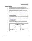
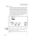
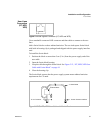
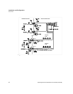
Setup See Figure 2.10.
1. Connect power supplies to be controlled via the CANbus network. Connect the
power supplies in a daisy chain by linking the first power supply to the second
using one cable, and then the second to the third using a second cable and the
second CAN port. Continue making connections in this fashion until all the
power supplies are connected. Terminate the bus at both ends, using the unused
CAN ports, with 120 ohm, 1/4 Watt resistors (included) across the CAN HI and
CAN LO signals (Pins 1 and 3). See Table 2.2, “CANbus Pins,” on page 36.
2. At least one power supply must be connected to a PC via GPIB for multichannel
functionality. Configure each of the power supplies with a unique address, as
described in the configuration section. Addresses may be in the range 1 to 50
inclusive. Record the address of each unit for future reference.
3. Turn the power supplies on one at a time.
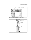
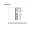
Figure 2.10Connections for Multichannel Operation
Using
Multichannel
Operation
Once the power supplies have been configured and connected, you may power them
on.
Power supplies controlled via multichannel have full capabilities, including
changing REM/LCL modes and calibration.
Any power supply may send multichannel commands, if they are connected to a PC
via GPIB.
GPIB
Connection