Release 2.1 69
Section 4. Status Registers
Overview
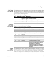
The Status Register structure is mandatory for SCPI and IEEE 488.2 compliance.
The register bits are defined by the SCPI and IEEE 488.2 standards.
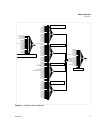
Each status register has a Condition, Event, and Enable register and transition filters.
See “Status Register Commands” on page 81 for commands to read or change their
values.
Condition
Register
Transitions of the condition register are automatic and reflect the condition of the
instrument at the moment. Reading a condition register has no effect on the contents.
Event
Register
The event register bits are set automatically to correspond with changes in the
condition register. The rules are dependent on the positive and negative transition
registers. Reading an event register clears it. The *CLS command clears all event
registers.
Enable
Register
The enable register enables reporting of the event bits to the summary bit or the status
byte. The contents of the enable register are unchanged by *CLS and *RST.
Transition
Filters
A positive transition filter allows an event to be reported when a condition changes
from false to true. Setting both positive and negative filters to TRUE allows an event
to be reported any time the condition changes. Clearing both filters disables event
reporting.
The contents of transition filters are unchanged by *CLS and *RST.
The status registers maybe be divided into 4 categories, the operation status registers,
the questionable status registers, the standard event status register and the status byte.
The default setting for all transition filters is to report only positive (FALSE to
TRUE) transitions.
OPERation
Status
Register
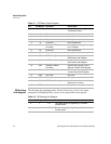
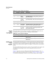
The operation status register is a 16-bit register which contains information about
conditions which are part of the power supply’s normal operation.


