


Installation and Configuration
4 153553
For use by qualified technicians only
5. Connect the Ethernet cable from the computer network to the
unprotected connection on the Ethernet surge protector.
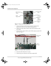
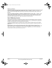
6. Connect the orange cable (U1002) to the U1002 connector on the
CCU board.
7. Connect the blue cable (U1001) to the U1001 connector on the CCU
board. See Figure 3.
8. Secure the cable with plastic tie wraps.
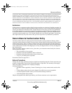
9. Connect the power connector to the power supply cable.
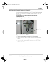
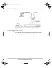
Figure 2
Ethernet Kit Cable Connections
Ethernet
Surge
Protector
Power
Connector
Fiber Optic
Cable
Ethernet
Cable
RS232/Fiber
Adaptor
Power
Supply Cable
Figure 3
CCU Board Cable Connections
CCU
Board
Fiber Optic
Cable
Ethernet.book Page 4 Thursday, May 29, 2008 4:20 PM