


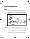

Current Sharing
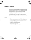
Overview
20 Operating Manual for XDC Series Slave Power Supply
CANbus
Setup
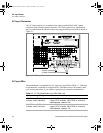
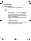
The CANbus port is a one male, one female DB9 connector to support “daisy chain”
connections. The CAN (Controller Area Network) is an ISO standard (ISO11898)
for a serial communication network. Table 3.1 describes the pin functions. Pins 1, 4,
8, and 9 are not used. The CANbus is part of the optional GPIB/CANbus interface
card, which is required for communication between the master unit and its slave
units.
Table 3.1 CANbus Pins
Setup
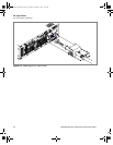
1. Connect power supplies to be controlled via the CANbus network. Parallel male
DB9 to female DB9 cables (N-1) are required. Each slave unit is shipped with
one male-female DB9 8 in. ribbon cable. Connect the CAN interface cards in
series, linking the first power supply to the second using one cable, and then the
second to the third using a second cable and the second CAN port. A single
ribbon cable with multiple connectors may be used instead of several cables for
ease of connection. Terminate the bus at both ends with 120 ohm, 1/4 Watt
resistors (included) across the CAN HI and CAN LO signals (Pins 2 and 7). See
Table 3.1, “CANbus Pins,” on page 20.
2. The master power supply may be connected to a PC via RS-232 or GPIB.
3. Turn the power supplies on one at a time, starting with the master, and check that
the green “Power ON” LED on each slave unit is lit. As each slave is turned on,
it will automatically configure itself with a sequential unique address. The
address is retained in non-volatile memory.
Note: Only the first 4 slave units powered on will current share.
Note: Only units with the same output ratings will current share.
Pin # Function
1 Not used
2 CANLO
3 Ground
4 Not used
5 Ground
6 Ground
7CANHI
8 Not used
9 Not used
TM-XDSL-01XN.book Page 20 Tuesday, November 5, 2002 3:22 PM