


RS232 Interface
RS232 Interface Connector
The 9-way D-type serial interface connector is located on the instrument rear panel. The pin
connections are as shown below:
Pin Name Description
1 - No internal connection
2 TXD Transmitted data from instrument
3 RXD Received data to instrument
4 - No internal connection
5 GND Signal ground
6 - No internal connection
7 RXD2 Secondary received data (addressable RS232 only)
8 TXD2 Secondary transmitted data (addressable RS232 only)
9 GND Signal ground (addressable RS232 only)
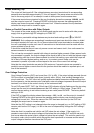
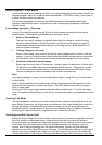
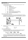
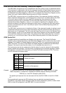
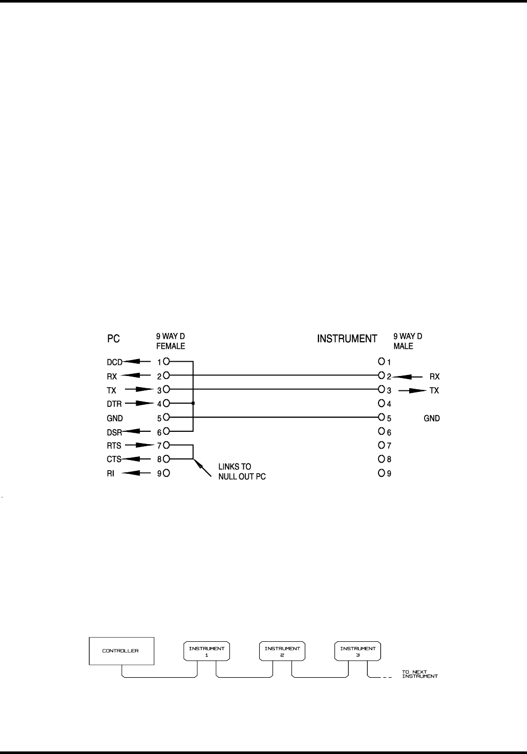
Single Instrument RS232 Connections
For single instrument remote control only pins 2, 3 and 5 are connected to the PC. However, for
correct operation links must be made in the connector at the PC end between pins 1, 4 and 6 and
between pins 7 and 8, see diagram. Pins 7 and 8 of the instrument must not be connected to the
PC, i.e. do not use a fully wired 9–way cable.
Baud Rate is set as described above in Address and Baud Rate Selection; the other parameters
are fixed as follows:
Start Bits: 1 Parity: None
Data Bits: 8 Stop Bits: 1
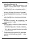
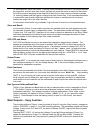
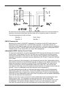
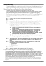
Addressable RS232 Connections
For addressable RS232 operation pins 7, 8 and 9 of the instrument connector are also used.
Using a simple cable assembly, a 'daisy chain' connection system between any number of
instruments, up to the maximum of 32 can be made, as shown below:
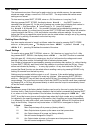
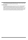
The daisy chain consists of the transmit data (TXD), receive date (RXD) and signal ground lines
only. There are no control/handshake lines. This makes XON/XOFF protocol essential and allows
the inter-connection between instruments to contain just 3 wires. The wiring of the adaptor cable
is shown below:
28