


GPIB IEEE Std. 488.2 Error Handling – Query Error Register
The IEEE 488.2 UNTERMINATED error (addressed to talk with nothing to say) is handled as follows.
If the instrument is addressed to talk and the response formatter is inactive and the input queue is
empty then the
UNTERMINATED error is generated. This will cause the Query Error bit to be set in
the Standard Event Status Register, a value of 3 to be placed in the Query Error Register and the
parser to be reset. See the Status Reporting section for further information.
The IEEE 488.2
INTERRUPTED error is handled as follows. If the response formatter is waiting to
send a response message and a
<PROGRAM MESSAGE TERMINATOR> has been read by the parser
or the input queue contains more than one END message then the instrument has been
INTERRUPTED and an error is generated. This will cause the Query Error bit to be set in the
Standard Event Status Register, a value of 1 to be placed in the Query Error Register and the
response formatter to be reset thus clearing the output queue. The parser will then start parsing
the next
<PROGRAM MESSAGE UNIT> from the input queue. See the Status Reporting section for
further information.
The IEEE 488.2
DEADLOCK error is handled as follows. If the response formatter is waiting to send
a response message and the input queue becomes full then the instrument enters the
DEADLOCK
state and an error is generated. This will cause the Query Error bit to be set in the Standard Event
Status Register, a value of 2 to be placed in the Query Error Register and the response formatter
to be reset thus clearing the output queue. The parser will then start parsing the next
<PROGRAM
MESSAGE UNIT>
from the input queue. See the Status Reporting section for further information.
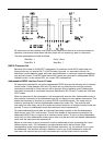
GPIB Parallel Poll
Complete parallel poll capabilities are offered on this instrument. The Parallel Poll Enable
Register is set to specify which bits in the Status Byte Register are to be used to form the
ist local
message The Parallel Poll Enable Register is set by the *PRE <nrf> command and read by the
*PRE? command. The value in the Parallel Poll Enable Register is ANDed with the Status Byte
Register; if the result is zero then the value of
ist is 0 otherwise the value of ist is 1.
The instrument must also be configured so that the value of
ist can be returned to the controller
during a parallel poll operation. The instrument is configured by the controller sending a Parallel
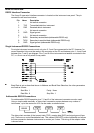
Poll Configure command (PPC) followed by a Parallel Poll Enable command (PPE). The bits in
the PPE command are shown below:
bit 7 = X don't care
bit 6 = 1
bit 5 = 1 Parallel poll enable
bit 4 = 0
bit 3 = Sense sense of the response bit; 0 = low, 1 = high
bit 2 = ?
bit 1 = ? bit position of the response
bit 0 = ?
Example. To return the RQS bit (bit 6 of the Status Byte Register) as a 1 when true and a 0 when
false in bit position 1 in response to a parallel poll operation send the following commands
*PRE 64
<pmt>, then PPC followed by 69H (PPE)
The parallel poll response from the instrument will then be 00H if RQS is 0 and 01H if RQS
is 1.
During parallel poll response the DIO interface lines are resistively terminated (passive
termination). This allows multiple devices to share the same response bit position in either wired-
AND or wired-OR configuration, see IEEE 488.1 for more information.
32