


Connections
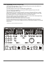
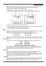
Front Panel Connections
The loads should be connected to the positive (red) and negative (black) terminals marked
OUTPUT 1, OUTPUT 2, or AUXILIARY.
Remote sense connections to the loads on Outputs 1 or 2, if required, are made from the
corresponding positive (+) and negative (−) REMOTE SENSE terminals. Remote sense
operation is selected from the keyboard or via a remote control interface (XDL 35-5TP only); the
REMOTE SENSE lamp is lit when remote sense is selected. Switching off remote sense returns
the instrument to local sensing at the output terminals.
The terminal marked
is connected to the chassis and safety earth ground.
Rear Panel Connections
Auxiliary Output Terminals
The front panel AUXILIARY OUTPUT terminals are duplicated on the rear panel with screwless
terminals marked AUXILIARY OUTPUT.
Main Output Terminals (XDL 35-5TP only)
The output and sense terminals are duplicated on the rear panel screw-terminal block marked
Output +, Output −, Sense + and Sense − ; these connections are paralleled with their front panel
equivalents.
Remote sense operation is selected from the keyboard or via a remote control interface. When
the rear panel terminals are used, remote sense should always be selected to ensure that output
regulation is maintained within specification.
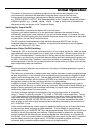
RS232 (XDL 35-5TP only)
9−pin D−connector compatible with addressable RS232 use. The pin connections are shown
below:
Pin Name Description
1
−
No internal connection
2 TXD Transmitted data from instrument
3 RXD Received data to instrument
4
−
No internal connection
5 GND Signal ground
6
−
No internal connection
7 RXD2 Secondary received data
8 TXD2 Secondary transmitted data
9 GND Signal ground
Pin 2, 3 and 5 may be used as a conventional RS232 interface with XON/XOFF handshaking.
Pins 7, 8 and 9 are additionally used when the instrument is used in addressable RS232 mode.
Signal grounds are connected to instrument ground. The RS232 address is set from the
keyboard.
12