


Patching In Signal Processors 35
MT8XII—Owner’s Manual
Patching In Signal Processors
Input channels 1 and 2 feature INSERT I/O jacks. These make is easy to patch external signal
processors directly into these two channels. Typically, compressors, limiters, and noise gates are
connected to this type of connection. Reverb, delay, and other effects processors can be used too.
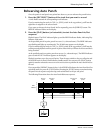
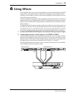
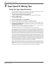
The INSERT I/O connections, which use TRS (Tip, Ring, Sleeve) phone jacks, are two-way con-
nections, with the tip carrying the output signal from the MT8XII to the external processor and
the ring carrying the output signal from the external processor back into the MT8XII. You need
special insert cables to do this. A wiring diagram for an insert cable is shown below.
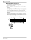
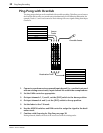
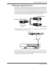
The following illustration shows how to connect an external processor to the MT8XII INSERTs.
Other equipment has been removed for clarity.
Once connected, operation is the same as normal. The signal source for the external processor
is taken after the channel’s EQ section. The output signal from the external processor is then
returned into the channel just before the fader. The processed signal can then be assigned to the
groups, sent to the Stereo bus, or to the auxiliary sends.
To processor's input
From processor's output
Connect to MT8XII INSERT I/O
Tip
Tip (send)
Ring (return)
Sleeve
Sleeve
Signal processor
Insert cable
Input Output
88
AC IN
POWER
ON/ OFF
OUT
SYNC INPUT LEVEL
IN +48V ON OFF
PHANTOM POWER
14
RL
21
RLRL
13 12 11 10 9 8 7
6
5 4 3 INSERT I/O 2 INSERT I/O 1
MIC/LINE INPUTLINE INPUT (UNBAL)STEREO INPUT (UNBAL)
AUX SEND
RL
STEREO OUT
RL
MONITOR OUT
RL
TAPE IN
8765 4321
21
TAPE OUT / GROUP OUT
MIC/LINE INPUT (BAL)
1:GND
2:HOT
3:COLD