


ENGLISH
MY8-SDI-D Owner’s Manual
9
with [—] in the list. Audio will be input to the slot channels, and will not be
muted regardless of the SW6 setting.
F
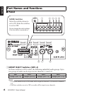
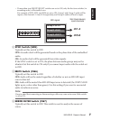
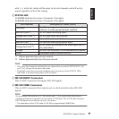
STATUS LED
[1-4] LED:
Indicates the status of channels 1 through 4
[5-8] LED:
Indicates the status of channels 5 through 8
Note:
•If an error that cannot be attributed to any channel has occurred, STATUS LEDs [1-4]
and [5-8] will provide the same indication.
•If multiple errors have occurred simultaneously, the priority of the STATUS LEDs
indication is the descending order of the list above.
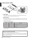
G
HD-SDI INPUT Connector
This is a BNC connector that inputs HD-SDI signals.
H
HD-SDI THRU Connector
This is a BNC connector that outputs non re-clock and active thru HD-SDI
signals.
Note:
We recommend that you use a 5C-FB coaxial cable
(*)
, or a coaxial cable that features
excellent performance equivalent to that of the 5C-FB cable. The 5C-FB cable transmits
HD-SDI signals over a distance of up to 100 meters.
* The attenuation of the 5C-FB cable at 750 MHz is approximately 20dB/100m.
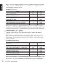
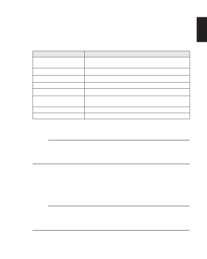
LED Indicator Description of Status (Error)
Off (dark)
No SDI-input signal is detected or being input. Alter-
natively, no audio group has been selected.
Red flash (Slow
*1
)
*1. Flashes approximately once per second.
SD-SDI signals are being input.
Orange flash (Slow
*1
)
An SDI input error has occurred.
Red Embedded audio is unlocked.
Red flash (Fast
*2
)
*2. Flashes approximately four times per second.
No selected audio group packet exists.
Orange flash (Fast
*2
)
A CRC error has occurred in the video signal sent to
the audio block.
Orange An error has occurred in the embedded audio packet.
Green Embedded audio is locked correctly.