


PES-1014 User’s Guide
Hardware Overview 2-1
Chapter 2
Hardware Overview
2.1 Front Panel
Refer to Appendix B
Safety Warnings and Instructions before installing the PES-1014.
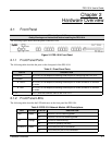
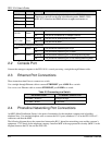
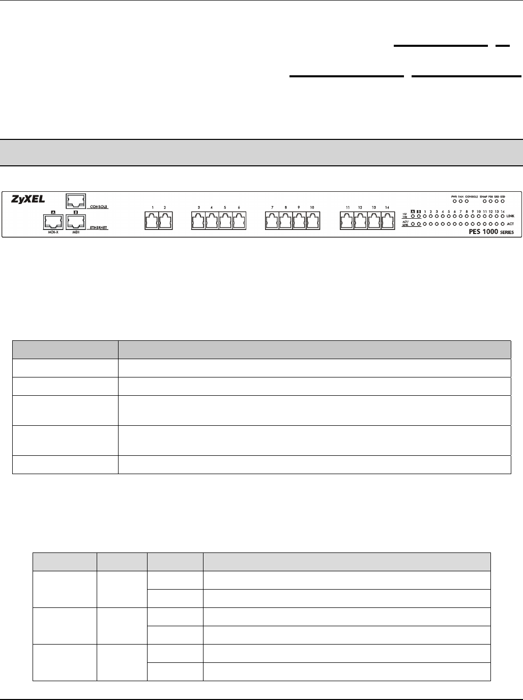
The following figure shows the front panel of the PES-1014.
Figure 2-1 PES-1014 Front Panel
2.1.1 Front Panel Ports
The following table describes the ports on the front panel of the PES-1014.
Table 2-1 Front Panel Ports
PORTS DESCRIPTION
CONSOLE An RJ-45 10/100 Mbps auto-sensing Ethernet port for configuring the PES-1014.
ETHERNET
A MDI-X An RJ-45 10/100 Mbps auto-sensing Ethernet port for WAN connection to a switch
or router.
B MDI An RJ-45 10/100 Mbps auto-sensing Ethernet port for WAN connection to a switch
or router.
1-14 RJ-11 ports that connect users to the PES-1014.
2.1.2 Front Panel LEDs
The following table describes the LED indicators on the front panel the PES-1014.
Table 2-2 PES-1014 Network Module LED Descriptions
LED COLOR STATUS DESCRIPTION
On The PES-1014 is receiving power.PWR Green
Off The PES-1014 is not receiving power.
On The fan is malfunctioning.FAN Orange
Off The fan is operating normally
On The CONSOLE port is connected.CONSOLE Green
Off The CONSOLE port is not connected.