


PES-1014 User’s Guide
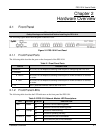
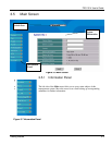
2-2 Hardware Overview
LED COLOR STATUS DESCRIPTION
SNMP Green
PSR Green
SRD Green
STD Green
These LEDs are used in a diagnostic test when the PES-1014 turns on.
They turn on and off one-by-one in the following order: SNMP> PSR>
SRD> STD. After this the SNMP will turn on again and remain on.
A, B (these are the Ethernet ports)
On The port is connected to a 100Mbps Ethernet.
10/100 Green
Off The port is connected to a 10Mbps Ethernet.
Blinking The port link is sending/receiving data.
ACT/LINK Green
Off The port link is down.
1-14 (these are the phoneline ports)
On The phoneline-networking link is up.LINK Green
Off The phoneline-networking link is down.
Blinking The phoneline-networking link is sending/receiving data.ACT Green
Off The phoneline-networking link is not sending/receiving data.
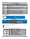
2.2 Console Port
Connect the manager computer to the PES-1014’s console port using a straight-through Ethernet cable.
2.3 Ethernet Port Connections
These instructions detail how to connect to a switch.
Use a straight-through Ethernet cable to connect ETHERNET port A MDI-X to a switch.
Use a cross-over Ethernet cable to connect ETHERNET port B MDI to a switch.
Table 2-3 Connecting to a Switch
EHTERNET PORT ETHERNET CABLE TYPE
ETHERNET A MDI-X Straight-through
ETHERNET B MDI Cross-over
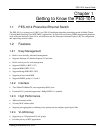
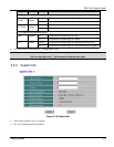
2.4 Phoneline Networking Port Connections
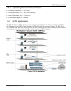
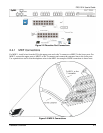
An MDF (Main Distribution Frame) is the point of termination for the telephone company and in-building
telephone lines. Use standard telephone wire to connect the RJ-11 ports (numbered 1-14) on the PES-1014 to Y-
connectors and then the MDF.
The following diagram shows the connections between the RJ-11 phoneline networking ports and the customer’s
equipment. “CO” stands for the telephone company. Install an MDF with surge protection circuitry (MDF-1 in the
diagram) between the CO line and the PES-1014.