


Chapter 3 Hardware Overview
XGS-4528F User’s Guide
46
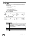
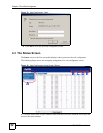
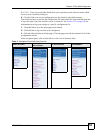
3.2 Rear Panel
The following figures show the rear panels of the AC and DC power input model switches.
The rear panels contain:
• A connector for the backup power supply (A)
• An optional uplink module (B)
• Two stacking ports (C)
• An RJ-45 out-of-band management port (D)
• An RS-232 management console port (E)
• A connector for the power receptacle (F)
•A power switch (G) (DC power input model only).
Figure 13 Rear Panel - AC Model
Figure 14 Rear Panel - DC Model
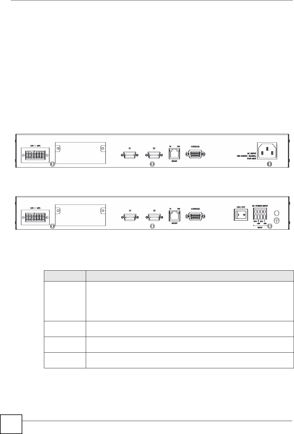
The following table describes the ports on the rear panel.
BDEFA
C
G
F
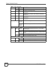
Table 2 Panel Connections
CONNECTOR DESCRIPTION
Optional two
10 GbE Ports
These ports are part of the optional uplink module which you can use to connect your
switch to other high-speed Ethernet switches in your network. Use 10 Gigabit Small
Form Factor Pluggable (XFP) transceivers to connect 1000Base-X fiber-optic cables
to these ports. See Section 3.1.3.1 on page 44 and Section 3.1.3.2 on page 45 for
information on installing and removing transceivers. See the EM-422 User’s Guide for
more information on this module.
Two stacking
ports
Connect these ports to other XGS-4528F switches for stacking using stacking cables.
Management
Port
Connect to a computer using an RJ-45 Ethernet cable for local configuration of the
Switch.
Console Port Only connect this port to your computer (using an RS-232 cable) if you want to
configure the Switch using the command line interface (CLI) via the console port.