Portable Printing Solutions S4500THS User Guide
Extech Instruments Corporation 285 Bear Hill Road, Waltham, MA 02451-1064 Phone: 1-877-4-EXTECH (439-8324) Fax: (781) 890-7864 Web site: www.extech.com
Copyright © 2005 Extech Instruments Corporation. All rights reserved including the right of reproduction in whole or in part in any form.
10
3.3 COMMUNICATIONS:
The S4500THS Printer is able to support two modes of communication
simultaneously – Either RS232 and IrDA (If Dip switch # 1 is ON) or
RS232 and 802.11b or Bluetooth (If Dip switch # 1 is OFF and Dip Switch
# 2 is ON).
Dip Switch # 2 is used to control the RS232 Port. If the Switch is turned
ON the RS232 port is disabled and if it is turned OFF the RS232 Port is
enabled. If RS232 interface is not required, disabling the port will save
battery power.
Bluetooth or 802.11b RF communication is available if optional daughter
boards are installed (802.11b). The printer can have either Bluetooth or
802.11b enabled but not both of them at the same time.
3.3.1 SERIAL COMMUNICATIONS SPECIFICATION:
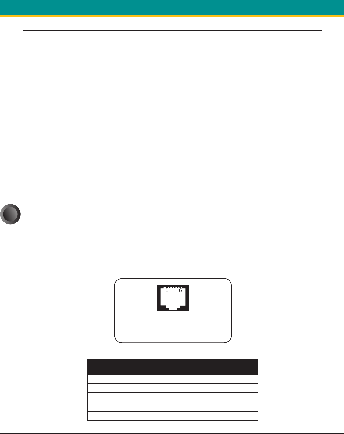
The RS232C Interface signals for the S4500THS Series printers are
terminated on a 6 PIN RJ type data connector located on the side of the
printer.
Six connections are provided from the Serial Interface to the host computer.
The TABLE 3 below lists the Serial Interface signals and pin outs on the RJ
connector and the connector pin locations are shown in
FIGURE 7.
A minimum of two connections are required for operation:
RXD – pin 3 and Common – pin 1
The communication Parameters: Baud rate, Data Bit and Parity must be set
same as the host device settings.
RJ DATA CONNECTOR SHOWING PIN
N
UMBER LOCATIONS
FRONT VIEW
FIGURE 7 - RJ DATA CONNECTOR
RJ25 Connector
Pin Number
Functional Description Signal Name
3 RS232 from Host (INPUT) RXD
2 RS232 from Printer (OUTPUT) TXD
6 Request to send from Host (INPUT) RTS
4 Clear to from Printer (OUTPUT) CTS
1,5 Logic common COM
TABLE 3 - 4500THS PRINTERS' SERIAL RS232C INTERFACE SIGNALS


