


Designing and Expanding the Network 2 - 7
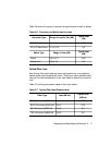
The following tables assist you in obtaining this information:
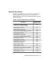
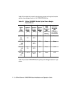
❑ Table 2-3 - Lists the optical power budget for the 10BASE-FB Module
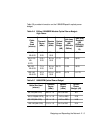
❑ Table 2-6 - List typical losses for connector and splice insertion loss
❑ Table 2-7 - Lists typical losses for various fiber cables
Calculating Maximum Link Distance
To calculate the maximum link distance allowed:
1. Determine the optical power budget for the 10BASE-FB
port (Table 2-3).
2. Subtract the optical power loss due to patch panels and splices
(Table 2-6) from the optical power budget for the 10BASE-FB port.
3. Subtract the dB loss/km rating of the fiber cable (Table 2-7) from the
remainder of step 2. If the result is greater than 0, the link distance is
valid.
4. If the device connecting to the 10BASE-FB Module does not have the
same optical budget as the 10BASE-FB Module, you must also
calculate the maximum link distance for the connecting device.
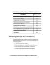
Determining Link Budget
To ensure link integrity, you should plan for worst case losses through the
end-to-end optical connection. The optical power budget represents a
worst case that assumes the transmitter is transmitting at the low end of its
range. When possible, 3Com recommends using Normal power.