


Designing and Expanding the Network 2 - 13
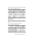
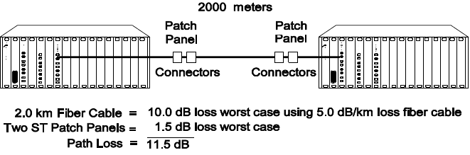
3. Use Table 2-7 to determine the worst case loss for the 62.5/125 fiber
cable (1700 meters x 5 dB = 8.5 dB). Add the losses to determine
total path loss. The total path loss is 9.5 dB. Because the overall
power budget is 10.0 dB, this leaves .5 dB to spare, so the link can be
made.
Ensure you do not overdrive a receiver (that is, the received optical power
level is not greater than the maximum received sensitivity level of the fiber
connector). In this case, the maximum possible transmit power (-17 dB +
3.0) is -14.0 dB (see Table 2-3). The power loss over the link is 9.5 dB. This
means that the power level of the signal will drop to -23.5 dB by the time it
reaches the receiver. Because the maximum receiver sensitivity is -8.0 dB,
there is no overdrive problem.
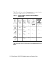
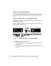
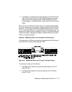
Example: 2000 Meter Fiber Link Through Two Patch Panels
In this example, two ONline concentrators are separated by 2000 meters of
fiber cable with two patch panels between them
.
Figure 2-2. 2000 Meter Fiber Link Through Two Patch Panels
To calculate the maximum link distance:
1. Use Table 2-3 to determine the optical power budget for 50/125
cable (5.5 dB).
2. Use Table 2-6 to determine the worst case loss for two ST patch
panels (1.5 dB).