


Installing and Operating the Module 3 - 21
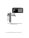
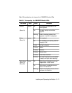
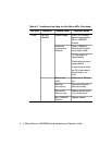
Table 3-5 describes how to interpret the 10BASE-FB Module LEDs.
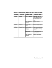
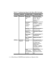
Table 3-5. Interpreting the 10BASE-FB Module LEDs
LED Name Color State Indicates
Activity
(Ports 1-4)
yellow Off No packets are received on the
fiber segment.
On Constant activity on the fiber
segment.
Blinking Module receives packets from
segment to which it is attached.
Status
(Ports 1-4)
green Off Port disabled.
On Port enabled or in standby and link
integrity is OK.
1 blink No light detected.
2 blinks Jabber.
3 blinks Partition.
4 blinks Remote fault.
5 blinks Invalid data received.
6 blinks Low light received (you can disable
it using Low Light switch setting).
Redundancy
(Ports 1-2)
(Ports 3-4)
green Off Redundancy is disabled; ports are
independent of each other.
On Redundancy is enabled between
ports 1 & 2 and 3 & 4.
Blinking Switchover has taken place or there
has been a link failure.