


Procedures
2 ATP-CNX-020 Rel. 1.2, Doc. Rev. 01.06
Aastra CNX Quick Installation and Setup Guide
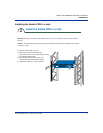
Preparing for the hardware installation
W
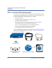
hat you need for a single installation
One Aastra CNX unit
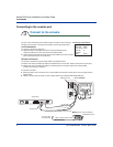
One AC power cable
One CompactFlash memory card
One set of rack mounting brackets with six (6) Phillips head screws
Truss head screws (not provided)
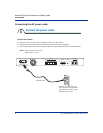
One to four RJ-48C T1/E1 cable(s) (not provided)
NOTE: T1/E1 Ports 1 and 2 are available for the 30-port unit and the 60-port unit.
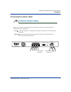
One 9-pin male DB-9 to female DB-9, RS-232 serial cable
One or two RJ-45 10/100BaseT Ethernet cable(s) (not provided)
(Optional) One 9-pin male DB-9 to female DB-25, RS-232 serial cable for
modem connections (not provided)
Prepare for hardware installation
1
Check the shipping contents
U
pon opening the shipping package, inventory the contents to be sure there are no missing
o
r damaged parts, as described in the Welcome section of this document.
D
etermine location of Aastra CNX (desktop or rackmount)
a
. If you are installing the Aastra CNX as a desktop unit, place it on a flat surface in close proximity
to your PC, skip Step 2, and perform Steps 3 through 8.
b
. If you are installing the Aastra CNX as a rackmount unit, proceed to Step 2.
*Tools required for rackmount installations
In addition to the parts listed above, the following tools are also required
when installing an Aastra CNX rackmount unit:
#2 Phillips screwdriver
Torque wrench
Nutdriver set