


AIM-16 Manual
Page 2-10
Manual MAIM-16.D1d
RTD Sensor Selection
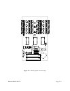
To configure a channel for RTD operation, install shorts in two selection points both labeled R"n",
where "n" is the channel number. These points are all located near the edge of the board furthest from
the connectors in the screw-terminal input area.
RTD Output Offset
For a board dedicated to RTD sensors, a negative output offset may be selected by installing a jumper
in the OFST position of the programming point labeled "OFST STD". This option is used in cases
where you wish to extend the range of an RTD channel.
If this feature is used, then the DIP switch S1 position labeled OSH determines the amount of the
offset. With OSH set ON, the offset is -10V and with OSH set OFF, the offset is -5V. See the
Considerations for RTD Sensors section in Sensor Interface of this manual for further information on
using RTD sensors.
Power Supply Selection
If you have ordered an AIM-16 with the P option (AIM-16P), there are two power supply jumpers.
These are labelled -VS and +VS. On the AIM-16P, the jumpers are installed in the +15V and -15V
positions. Moving these jumpers to the +12V and the -12V positions disables the on-board power
supply and connects the power supplied at the external I/O connector, pin1 for +VS and pin 20 for
-VS. The maximum allowable external voltage ±18V. It is mandatory that only a single +VS and a
single -VS jumper be used. When an AIM-16 is purchased without the P option, two shorts are
soldered at the -12 and +12 positions.