


Page A-1
Manual MAIM-16.D1d
Appendix A: Cabling and Connector Information
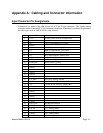
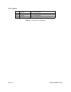
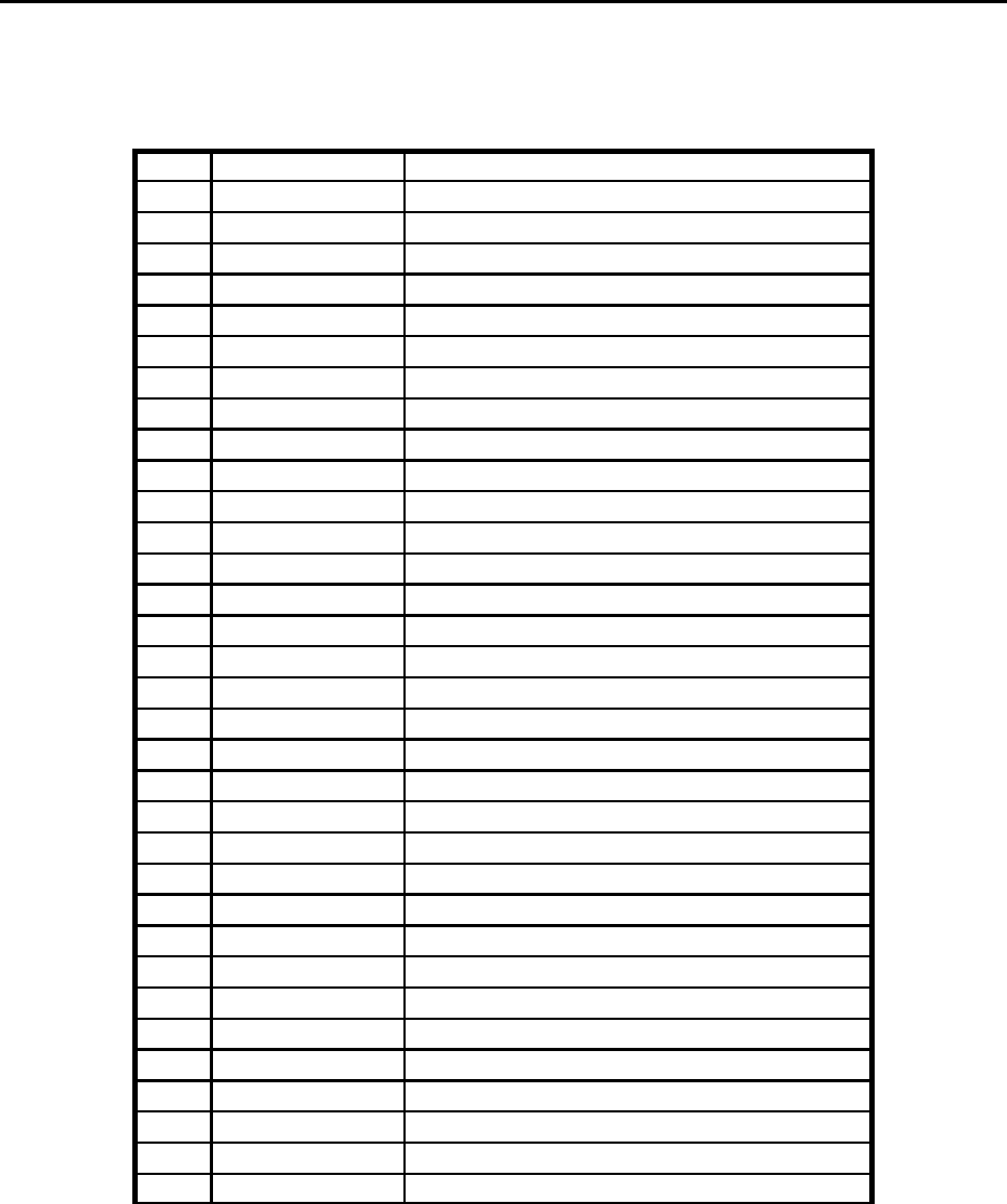
Input Connector Pin Assignments
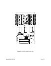
Connections are made to the AIM-16 card via a 37-pin D type connector. The female mating
connector can be a Cannon #DC-37S for soldered connections. Alternatively, insulation-displacement
flat cable types such as AMP #745242-1 may be used.
Pin Name Function
1 +VS +12VDC Power from the Computer Bus
2 unused
3 G0 LSB of programmable gain control
4 unused
5 G1 Bit 1 of programmable gain control
6 G2 MSB of programmable gain control
7 A0 LSB sub-multiplexer channel select
8 A1 Bit 1 sub-multiplexer channel select
9 A2 Bit 2 sub-multiplexer channel select
10 A3 MSB sub-multiplexer channel select
11 PWR GND Power (Digital) ground
12 unused
13 unused
14 unused
15 unused
16 unused
17 unused
18 L.L. GND Low Level (Analog) Ground
19 VREF +10.0VDC A/D reference from A/D card
20 -VS -12VDC Power from the Computer Bus
21 unused
22 unused
23 unused
24 unused
25 unused
26 unused
27 unused
28 REF GND A/D Reference Return
29 +5VDC +5VDC Power from the Computer Bus
30 CH7 IN Chl 7 Analog Output
31 CH6 IN Chl 6 Analog Output
32 CH5 IN Chl 5 Analog Output
33 CH4 IN Chl 4 Analog Output