


AIM-16 Manual
Page 4-2
Manual MAIM-16.D1d
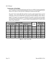
Considerations for RTD Sensors
Three-wire connection may be applied to an RTD sensor by adding two shorts per channel for each
sensor served. The locations for these shorts are labelled R0 through R15. For example, install two
shorts in the two locations labeled R2 if an RTD sensor is used at channel 2.
For extended range and resolution of measurements, it is common practice in RTD processing to offset
the sensor output in a negative direction. The AIM-16 allows a negative 10V offset, so that a zero
input to a channel provides a -10V output. In order to enable this feature install a jumper in the OFST
position of the programming point labeled OFST STD and place the DIP switch labeled OSH in the
ON position.
If the host A to D card is rated at ±5V full scale, install the OFST STD jumper as above but place the
OSH switch in the OFF position. This will reduce the offset to -5V.
While this offset increases the range and resolution of RTD operation, remember that it is a selection
that affects all channels on a given card.
Connections to an RTD sensor are as follows: the V+, I+ lead to the "+" input; the V- lead to the "-"
input; and the I- to the "GND" input.
If all of your sensors are RTDs, model AIM-16R is designed specifically for RTDs.
Considerations for Strain Gage Sensors
A ratiometric reading of a strain gage sensor requires input to two channels of an AIM-16 card. One
channel measures the sensor excitation while the other channel reads the sensor output. The host
computer computes the output as a ratio of the sensor output to sensor excitation. This requires
different gains for each signal, nominally a gain of 1 for the excitation and 200 for the signal. Thus,
strain gage measurement requires the use of programmable gain on an AIM-16 board.
Excitation for the strain gage(s) is available at a screw terminal block on the AIM-16. That excitation
is derived from the AD12-8's precision 10V reference voltage and can supply over 200mA current.
A jumper should be installed in the STD position of the programming point labeled "OFST STD".
When the STD position is selected, no offset is produced.