


Description of Hardware
1-5
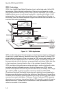
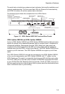
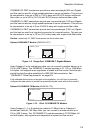
The switch also includes key system and port indicators that simplify installation and
network troubleshooting. The front panel has LEDs for Ethernet link status/activity
and VDSL link status, as well as system status indicators.
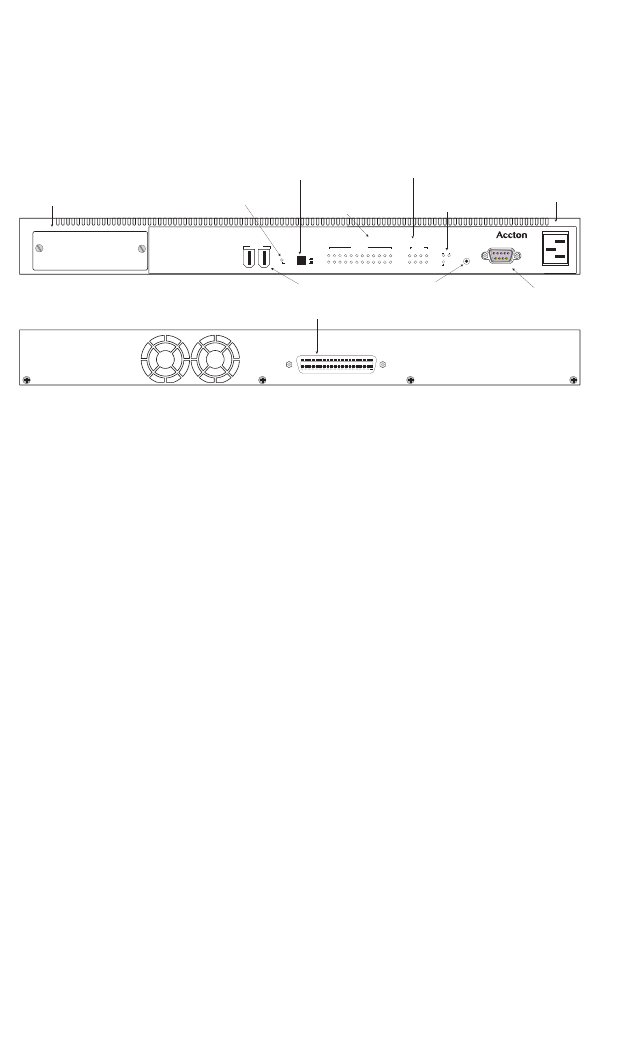
The following figure shows the components of the VDSL Switch.
Figure 1-2. VDSL Switch-VS2512A Front and Rear Panels
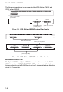
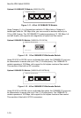
VDSL Splitter-VM2524 and VDSL Splitter-VM2548
Accton’s VDSL Splitter-VM2524 and VDSL Splitter-VM2548 combine data and voice
signals for delivery over standard telephone cable to multiple users in residential or
commercial buildings. Data signals from the VDSL Switch port (rear panel) are
combined with phone signals from the PBX port (rear panel) and then passed to
multiple users over the VDSL Line port (front panel). The VDSL Splitter-VM2524 can
support up to 24 line/users. The VDSL Splitter-VM2548 can support up to 48 line/
users.
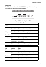
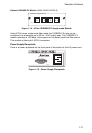
Two VDSL Switch-VS2512A units can be connected to one VDSL Splitter-VM2524,
or four can be connected to one VDSL Splitter-VM2548, with “Y” cables, via the
VDSL Switch port.The switch is connected directly to your ISP with fiber optic cable.
The RJ-21 PBX port on the rear panel connects to PBX/MDF equipment that leads
to your POTS (Plain Old Telephone Service) provider. The RJ-21 VDSL Line port on
the front panel connects to a punch-down block or patch panel that distributes phone
lines to individual users in your building.
VDSL
VDSLPort
StatusIndicators
StackingPorts
ExpansionSlot
1000BASE-T, 1000BASE-SX,
100BASE-FX,
or10/100BASE-TX modules
1000BASE-XGBIC,
ConsolePort
Usethis forconsoleconnections
PowerSocket
VDSLConnector(to Splitter)
SystemStatus
Indicators
StackingMaster
Push-button
StackingMaster
StatusIndicator
ResetButton
EthernetPort
StatusIndicators
VDSLSwitch-VS2512A
Reset
Power
Stacking
Diag
Master
On
Off
Up Down
Stacking
VS2512A
Expansion Module
100-240V ~ 50-60 Hz 1A
Console
2 3 4 5 6 7 8 9 10 11 12
VDSL
1
Activity
Link
Activity
Link/Speed
1234
Ethernet