


Mounting
3-3
• Power requirements: 100 to 240 VAC (± 10%) at 50 to 60 Hz (± 3Hz). The switch
and splitter power supplies automatically adjust to the input voltage level. Make
sure that a properly grounded power outlet is within 2.5 m (8 ft) of the switch and
splitter.
• The switch and splitter should be located in a cool dry place, with at least 10 cm
(4 in.) of space on the sides for ventilation.
• Place the switch and splitter out of direct sunlight, and away from heat sources or
areas with a high amount of electromagnetic interference. The temperature and
humidity should be within the ranges listed in the specifications.
• If you intend to mount the switch and splitter in a rack, make sure you have all the
necessary mounting screws, brackets, bolts and nuts, and the right tools.
• Check if network cables and connectors needed for installation are available.
• Be sure the splitter is within reach of the punch-down blocks (or patch panel) for
rear panel connections and within reach of the VDSL switch for front panel
connections.
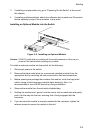
Installing Optional Modules: Before mounting the switch, be sure you install any
optional modules. If you have purchased an optional slide-in 1000BASE-SX,
1000BASE-T, 1000BASE-LX, 1000BASE-X GBIC, 10/100BASE-TX or
100BASE-FX media expansion module, install it now, following the instructions
provided on page 3-5.
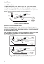
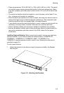
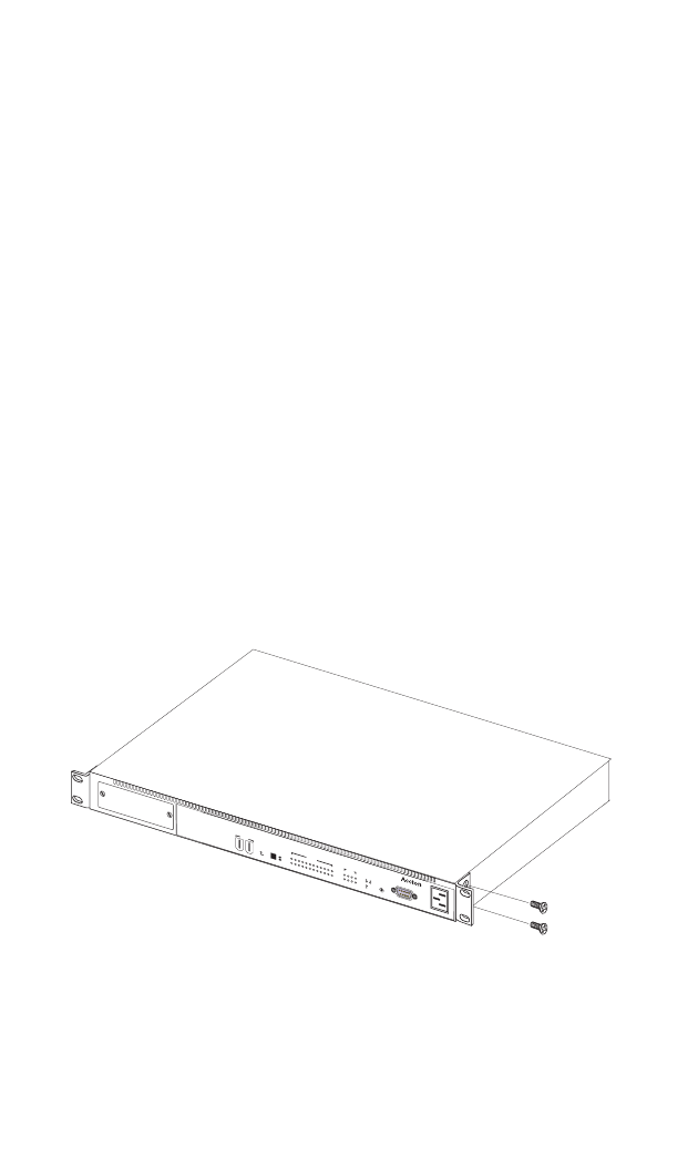
To rack-mount devices:
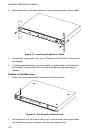
1. Attach the brackets to the device using the screws provided in the Bracket
Mounting Kit.
Figure 3-2. Attaching the Brackets
VDSLSwitch
-
VS2512A
R
e
s
e
t
P
o
w
e
r
S
t
a
c
k
i
n
g
D
i
a
g
M
a
s
t
e
r
O
n
O
f
f
U
p
D
o
w
n
S
t
a
c
k
i
n
g
VS2512A
1
0
0
-
2
4
0
V
~
5
0
-
6
0
H
z
1
A
C
o
n
s
o
l
e
234567891
0
111
2
VDSL
1
A
c
t
i
v
i
t
y
L
i
n
k
A
c
t
i
v
i
t
y
L
i
n
k
/
S
p
e
e
d
1234
Ethernet
E
x
pan
sion
M
o
du
le