Powering On the Switch
3-7
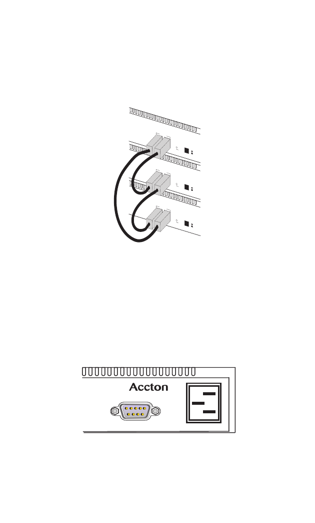
Connecting to the Stack’s Backplane
Plug one end of the provided stack cable in the “Down” port of the top unit and the
other end to the “Up” port of the next unit. Repeat this step for each unit in the stack.
Form a simple chain starting at the “Down” port on the top unit and ending at the
“Up” port on the bottom unit (stacking up to 8 units).The VDSL Switch-VS2512A
supports a wrap-around stacking feature. If a connection is made between the
“Down” port of the bottom switch in the stack and the “Up” port of the top switch,
then all switches in the stack will remain connected, even if one fails.
Figure 3-7. Connecting to the Stack’s Backplane
Select the Master unit in the stack by pushing the push button in on the front of the
switch.
Note: Only one switch in the stack can act as Master.
Powering On the Switch
To connect a device to a power source:
1. Insert the power cable plug directly into the receptacle located at the front of the
switch.
Figure 3-8. Power Receptacle
2. Plug the other end of the cable into a grounded, 3-pin socket.
Note: For International use, you may need to change the AC line cord. You must use
a line cord set that has been approved for the receptacle type in your country.
Master
On
Off
Up Down
Stacking
Master
On
Off
Up Down
Stacking
Master
On
O
ff
Up Down
Stacking
VDSLSwitch-VS2512A
VS2512A
100-240V ~ 50-60 Hz 1A
Console


