


71 TravelMate 240/ 250
7. See “Removing the ODD Module(1)” on page 69.
8. See “Removing the HDD Bracket” on page 69.
9. See “Removing the Main Board” on page 70.
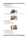
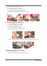
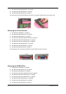
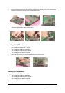
10. Remove the two screws that fasten the DC board. Then detach the DC board from the lower case.
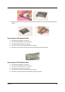
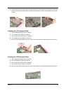
Removing the I/O Port Bracket
1. See “Removing the Battery” on page 52.
2. See “Removing the Middle Cover” on page 56.
3. See “Removing the Keyboard” on page 63.
4. See “Removing the Floppy Disk Drive Module” on page 67.
5. See “Removing the VGA Heatsink Plate” on page 68.
6. See “Removing the CPU Heatsink Plate” on page 68.
7. See “Removing the ODD Module(1)” on page 69.
8. See “Removing the HDD Bracket” on page 69.
9. See “Removing the Main Board” on page 70.
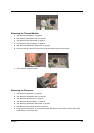
10. Remove the four hex screws to detach the I/O port bracket from the main board.
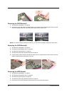
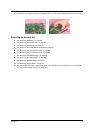
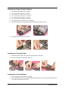
Removing the PCMCIA Slot
1. See “Removing the Battery” on page 52.
2. See “Removing the Middle Cover” on page 56.
3. See “Removing the Keyboard” on page 63.
4. See “Removing the Floppy Disk Drive Module” on page 67.
5. See “Removing the VGA Heatsink Plate” on page 68.
6. See “Removing the CPU Heatsink Plate” on page 68.
7. See “Removing the ODD Module(1)” on page 69.
8. See “Removing the HDD Bracket” on page 69.
9. See “Removing the Main Board” on page 70.