


Chapter 3 80
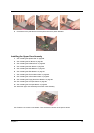
13. See “Installing the Processor” on page 91.
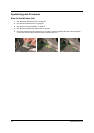
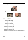
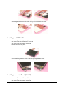
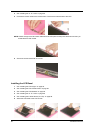
14. Place the thermal module to the main unit.
15. Secure the thermal module with the four screws. Then connect the thermal module cable to the main
board.
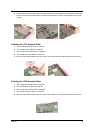
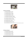
Installing the MimiPCI Card Plate
1. See “Installing the Speaker Set” on page 86.
2. See “Installing the DC Board” on page 86.
3. See “Installing the PCMCIA Slot” on page 86.
4. See “Installing the Main Board” on page 86.
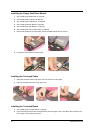
5. See “Installing the HDD Bracket” on page 87.
6. See “Installing the ODD Module” on page 87.
7. See “Installing the CPU Heatsink Plate” on page 88.
8. See “Installing the VGA Heatsink Plate” on page 88.
9. See “Installing the Floppy Disk Drive Module” on page 88.
10. See “Installing the Touchpad Cable” on page 89.
11. See “Installing the Touchpad Board” on page 89.
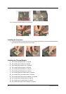
12. See “Installing the Upper Case Assembly” on page 90.
13. See “Installing the Processor” on page 91.
14. See “Installing the Thermal Module” on page 91.
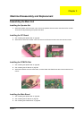
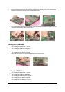
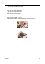
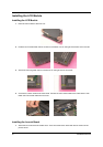
15. Place the mini PCI card plate to the main unit. Secure the mini PCI card plate with the three screws as the
picture shows.