


3-6 Machine Maintenance Procedures
Maintenance Flowchart 0
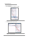
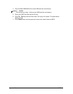
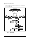
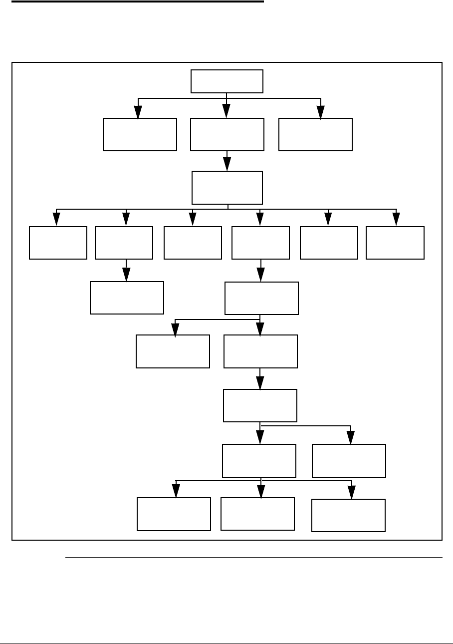
The flowchart in Figure 3-1 shows a graphic representation of the module removal and
installation sequences. It shows information on what components may need to be removed
and installed during servicing.
Figure 3-1. Maintenance Flow
Battery
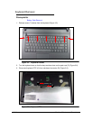
Keyboard ODD Module
USB
Board
Lower Cover
WLAN
Module
Bluetooth
Module
Mainboard
RTC
Battery
SD Dummy
Card
Thermal
Module
HDD Module
LCD Module
LCD Bezel
LCD Panel
Speaker
Camera
Antennas
DIMM
Modules
LCD Brackets
LVDS Cable